About Electrical Logical Systems | ||
| ||
![]()
Concept
The following is a summary of what the electrical logical objects stand for.
An electrical logical system is based on:
- Electrical components:
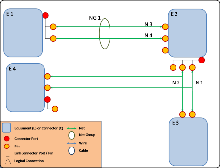
- Connector, Equipment: electrical components aggregating connector ports, terminal connectors
- Net, net group: specification for electrical connectivity between two components. A netgroup can gather nets and other net groups
- Wire, cables: electrical connectivity between two components. A cable can gather wires and other cables.
- Electrical ports:
- Connector port: contact point gathering pins and/or connector ports
- Pin: terminal contact point.
View of an electrical logical system:
- Harnesses:
In addition to the model described above, the harness object is used to define a wire/cable networks. A harness reference aggregates electrical wires/cables and, in a typical case, electrical connector components that stand for the end of the harness. Harnesses are connected together through connector components.
From an electrical point of view, all harnesses are aggregated into a harness networks. This network is interpreted in the electrical harness 3D applications.
View of a harness:
View of a harness network:
![]()
RFLP Structure Tree
RFLP is a specification tree allowing you to build an electrical logical system. It stands for Requirement, Functional, Logical and Physical.
In the RFLP tree of an electrical system, all electrical objects belonging to the system are grouped under an Electrical node then divided by category:
- Equipments
- Busbars
- Connectors
- Harnesses
- Nets (for nets and net groups)
- Wires (for wires and cables)
- Ports (for connector ports and pins)