Routing between Points, Devices and Supports | |||||||
|
| ||||||
Route between Points, Devices and Supports
You can route branches between points, electrical devices, through supports as well as along existing curves and surfaces.
Double-click the electrical geometry in the specification tree to activate it.

Click Route Definition.
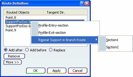
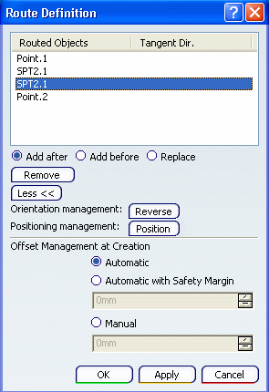
The Route Definition dialog box appears:
Select a first device.
Moving the pointer over a device displays segment connection points or cavity. You can select:
A red arrow appears in the geometry area showing the direction of tangency. If necessary, click the arrow to reverse this direction.
Important: Only the first and last route points can be connected to another branch or a device. Select a support.
Moving the pointer over a support displays annotations showing the possible entry points of a support.
You can select:
-
A support.
If you select a multi-support instead of a label, the section closest to your selection point is selected.
- Or, a label.
If necessary, adjust the direction and position of the branch going through the support.
-
A support.
Select other desired points, devices and supports.
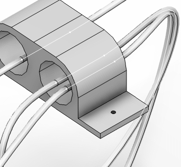
The final branch looks something like this:
If you want to route your branch in the support more than once, right-click an object and select a section.
In our case, two sections are represented but if your support only contains one hole, then you don't need to choose a section.
Select the object once again.
You can see a preview of your branches.
Optional: If you want to arrange your segments, select your product and go to Tools > Segment Arrangement > Arrange Segments or click Position in the Route Definition dialog box.
![]()
Change the Orientation and Position of Supports
You can change the orientation and position of the supports. The way through and the position of the branch inside supports are specified when creating supports.
When routing, an arrow appears showing which way the branch will be routed through the support.
-
If necessary, select the arrow to invert the tangent direction. You can also change the orientation by clicking Reverse in the dialog box (under More>>).
When routing, you can also manage how the branch is positioned with respect to the support:
- Click More>> in the dialog box.
- Click Position.
- In the Point Definition dialog box that opens, change the H and V values,
- Or click anywhere in the geometry area and reposition the point using the 3D manipulator.
- Click OK when done to return to the Route Definition dialog box.
Important: - Slack is ignored when branches are routed through supports.
- In case of adaptive supports, the Position button in the Route Definition dialog box will be unavailable.
Note: After selecting the Position button, you can see either the Point Definition or the Arrange Segments window. It depends on the following conditions:
- If the branch has been routed in the support in V5 and the support
has been upgraded
via the
Post-Process (Tools > Finalize
Data Import), the Point Definition dialog box appears:
- If a branch (already routed or not) is routed in V6 in this support, the Arrange Segments dialog box appears:
- If a branch has been routed after V5R17 in a support that has been saved after V5R17, the Arrange Segments dialog box appears.
For more information about reference support part imported via FBDI, refer to Electrical Library File-based Design Import.
![]()
Add a Tangent Constraint at a Route Point
You can add tangent constraint at a route point to maintain the tangency of the branch.
Select the tangent direction:
- In the Tangent direction box, select a line or plane for the Explicit constraint type. The contextual menu is available you.
- In the Element box, select a curve for the From curve constraint type.The tangent direction is that of the selected curve.
The example below shows an edge being selected.
- In the Tangent direction box, select a line or plane for the Explicit constraint type. The contextual menu is available you.