About Routing | ||
| ||
Routing
Routing is defined to create flexible curve represenation.
You can route branches between points, electrical devices, through supports as well as along existing curves and surfaces.
Route points are defined using Point
![]() . They let you position the branch and control its direction. Points
are created on-the-fly when routing branches on
surfaces.
. They let you position the branch and control its direction. Points
are created on-the-fly when routing branches on
surfaces.
Plane
![]() and
Line
and
Line
![]() commands
are available to assist you route branches.
commands
are available to assist you route branches.
The start or end route points of existing branches can be used to define new branch routes. However, when branching out from existing branches, branch points are created on-the-fly.
For more information about creating point, plane and line, refer to Generative Shape Design User's Guide: Creating Points, Creating Planes and Creating Lines.
![]()
Context
When routing, the context is defined by the parent common to the harness bundle and all already-routed objects.
If you subsequently select an object
outside this context, the system proposes to automatically update the context
for you. 
![]()
Specification Tree Selection
You can select devices and supports in the specification tree if the selection is not ambiguous.
Ambiguous means that there are several ways the branch can be routed, for example:
- Connectors with two or more segment connection points
- Supports with two or more entry points.
In this case, the pointer appears like this
![]() and the selection
cannot be made in the specification tree.
and the selection
cannot be made in the specification tree.

The selection can only be made in the geometry area: the connection point closest to the selection is taken into account for the branch route.
The pointer appears like this
![]() when the
selection is possible both in the specification tree and the geometry area.
when the
selection is possible both in the specification tree and the geometry area.

The system automatically selects the segment connection point (for connectors and backshells) or the entry point (for supports) as if you had made the selection in the geometry area.
![]()
Branch Shape Computation
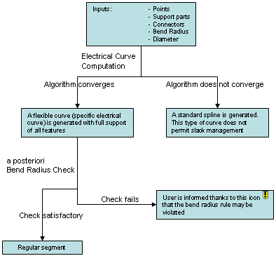
By default, the standard algorithm is used to compute branches and give you the best possible branch shape.
Each time you click Apply or OK during the definition phase, or if you update the branch after any parameter modification, the standard algorithm is run.

The
![]() symbol identifies branches built using standard splines in the specification
tree.
symbol identifies branches built using standard splines in the specification
tree.
The  symbol identifies branches which have been switched to mechanical splines.
Note: To give your segments a more realistic behavior that reflects segment stiffness, use the FLEX algorithm.
| Important: After editing the Bundle Segment of a regular curve, if two red spots appear on the branch shape computation, it means that the standard algorithm (Bend Radius / Diameter) is not respected between these two points. For more information, refer to About Routing, Branch Shape Computation, in the Electrical 3D Installation User Guide. |