Routing on Surfaces between On-the-Fly Points | ||||||
|
| |||||
Routing on Surfaces
You can route the branch on the surface.
The Route Definition dialog box appears:
Press Ctrl to display a manipulator and the tangent direction.
The manipulator follows the surface when you move it. The point is positioned perpendicular to the surface, and is located by default at a distance from the surface equal to the segment radius.
A number of options let you manage the offset distance from the surface. To route branches whilst managing this distance, see Managing the Offset Distance.
Click successively to create points and define the flexible curve.
Note: The green arrow shows the tangent direction of the curve at the point you are about to create and the red arrow that at the point just created.
Release Ctrl to end the flexible curve definition.
You can modify the route by adding, replacing or removing points as well as modifying the tangent direction.
![]()
Managing the Offset Distance
You can manage the distance between on-the-fly points and the surface when routing branches.
Press Ctrl and start to define the flexible curve with an automatic offset:
Click More>> to access Offset management at creation options:
- The default value is set to Automatic.
- For circular profiles, the offset is equal to the segment radius at all route points. This allows you, for example, when slack is 0mm, to keep the segment in contact with the surface.
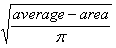
- For non-circular profiles, the offset is equal to
an equivalent radius computed as follows:
- Automatic with safety margin: the offset is equal to the segment radius (or equivalent radius in the case of non-circular profiles) plus the value entered.
- Manual: lets you specify a different offset at a selected point of the route.
Note: In Automatic, the branch will remain in contact with the surface if the branch is modified, but not if the surface is modified.
- The default value is set to Automatic.
Press Ctrl again to continue the route.
Note: You can change the mode at one or more points. If you then come back to automatic offset management, the result looks like this: