About Connectors and Connection | ||
| ||
Connectors
There are several kinds of connectors and connections in Modelica. Here is a summary of them.
For further details, refer to Modelica language specifications (available at www.modelica.org).
- Standard connector
- From one simple connector to another. Requires no additional information.
Refer to Creating a Standard Connection.
- Array of connectors
- If one of the connectors in the connection is an array, then one of the connectors in the array needs to be selected for the connection.
The array dimension can either be a number or a simple parameter:
ConnType a [3];
parameter Real n = 2;
ConnType b[n];
An array of connectors can be connected to one or several logical ports.
- Expandable connector
- The connection can be either to the whole bus connector, or to one of its sub-components or to a new sub-component added on the fly.
Components of expandable connectors are automatically treated as connectors.
- Nested connectors
- A connector that contains sub-connectors. The connection can be either to the top connector or to one of the sub-connectors.
- Bus Modeling
- It is possible to draw connections from a connector back to itself. This allows signals on a bus to be re-routed.
![]()
Logical Connection
From the Dynamic Behavior Modeling workbench, a logical behavior can be edited. The logical ports and behavior ports can be connected together, since the logical ports exist in the Dynamic Behavior Modeling workbench.
For this, logical ports must be synchronized from the Functional Logical Editor workbench:
- Automatically: If you insert a behavior under a logical component that aggregates at least one port.
- Manually: for all other cases, using the Ports Mapping command.
Refer to Creating a Connection to a Logical Port.
Also refer to the Functional and Logical Behavior chapter in the VPM Functional Logical Editor User's Guide.
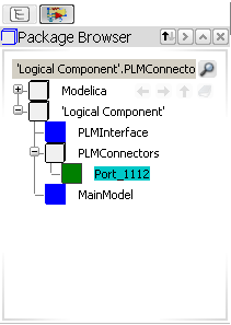
Logical ports appear and can be activated from the PLMConnectors package, in the Package Browser:
| Important: After duplication, a logical port has no type. When connected to a behavior port, the logical port inherits the type of the behavior port, through an Extends clause. |
![]()
Check of Connections
When a connection has been defined, the following checks are automatically performed:
- Two connections between the same connectors are not allowed.
- The connectors at each end of the connection are checked for compatibility. If incompatibility is detected, an error message displays the declarations of the two connectors. The connection must be cancelled.
- If a model singularity is caused by incorrect or missing connections, no additional diagnostic is given.
- Diagnostic for connections set with multiple sources for the same causal signal, or no source for a causal signal.
Note: In some models, the missing equation for the input is provided textually. Please change these models to use source-blocks instead.
![]()
Cross-connection Management
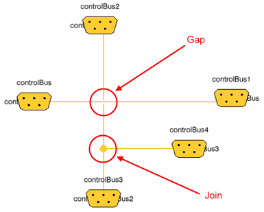
You can display a gap at the crossing point of two different connections, and a join (drawn as a bullet) at the separating point of two connections linked to the same port.
For this, use the Gap Bridge option from Tools > Options > Systems > Dynamic > Editor tab.