This section describes how to connect an expandable connector to another connector.
Create a behavior diagram containing at least one expandable connector.
In this example we have used the following components from the Modelica Standard Library:
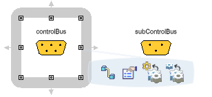
- Modelica.Blocks.Examples.BusUsage_Utilities.Interfaces.ControlBus
- Modelica.Blocks.Examples.BusUsage_Utilities.Interfaces.SubControlBus
(Both of these components are expandable connectors.)

Select a connector and then click Connection  from the Balloon contextual toolbar or from the Authoring toolbar.
A connection line appears and follows the cursor.

Select the connector with which you want to create a connection.
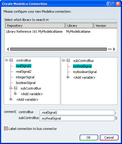
The Create Modelica Connection dialog box is displayed.
To create a connection between nodes in the connector trees, in the central window of the Create Modelica Connection dialog box, select a node from the left hand tree and a node from the right hand tree.
The nodes you select are displayed in the connect statement at the bottom of the dialog box.
In this example a connection has been made between realSignal1 of controlBus and myRealSignal of subControlBus.

To create a connection between a node and a variable in the connector trees:
- In the central window of the Create Modelica Connection dialog box, select the node from the appropriate tree.
- In the top window of the dialog box, select the library which contains the variable. If necessary use Search to locate and load a library.
- Click + next to a node to expand the list of available variables.
- Either select a variable, or click <Add variable> and then enter your variable name in the connect statement at the bottom of the dialog box.
The node and variable you select are displayed in the connect statement.
To include a label on the connection in the diagram, select the Label connection to bus connector check box.
When finished, click OK.
- The connection is created.
- The Create Modelica Connection dialog box closes.