In the PPR Context, select the operation to which you
want to attach the time analysis.
Click Create Time Analysis  .
.
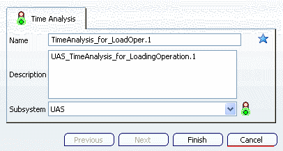
The Time Analysis dialog box appears.
Enter a name and description for the time analysis and select UAS as the desired subsystem.

Note:
Always
give a meaningful name and a short description for the time analysis. This can help you to find an analysis later.
Click Finish.
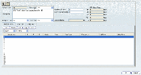
The STM - UAS Subsystem dialog box opens. This dialog box enables you to define
and modify the time analysis. The analysis criteria are entered
by means of a spreadsheet.

Note:
You
can create time analysis for the following subsystems in a similar way:
STD, UAS,
MEK, GTE, MTM-1, MTM-2, RWF, SAM, and MOST.
Enter AA1 in the Code
cell in the first row of the spreadsheet.
The other columns in the first row are filled accordingly.

Enter more information in the following rows for the Code
column.
The respective column values will be displayed for the entered codes. For the last row, the Total Time column remains empty but the Setup Time column is filled.

Click Calculate  .
.
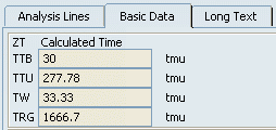
The total Analyzed Time is calculated. The STM_Base Times namely Human Time (TTB), Machine Time (TTU), Waiting Time (TW), Total Time (TG) and Setup Time (TRG) are also displayed.

The Calculated Times in the Basic Data tab are also displayed.

Click OK to save the time analysis.
The time analysis is attached to the previously selected operation.
Switch to the Manufacturing System Definition workbench and use the Manufacturing System Gantt chart to set the Time Type Visualization to Analyzed Time.
The Gantt chart will then show the analyzed time for all operations.
For more information, see Manufacturing System Definition User's Guide: Time Types on Operations.