Managing Planning Break Exceptions | ||||||||
|
| |||||||
Click Planning Break
 in the Operation toolbar.
The Planning Break Management dialog box appears.
The selected design unit is displayed in the Geometry box. All the structural objects along with their system status are listed in the Status tab.
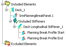
Right-click and select IN with Planning Break.
The PB is displayed in the Overridden column against the selected object.
Also, a new node with the same name as of the selected object is created in the specification tree below the Included Stiffener node.
Edit the planning break.
You can perform the following operations:
- Click IN or OUT to change the status to in or out.
- Select another limiting object. The selection is listed in the Planning Breaks area.
Note: You can select a surface, a reference plane, a volume and a curve. A curve can be defined using the Sketcher workbench.
- Enter the offset value in the Offset box, to set the offset for the limiting object.
Note: The Offset box is anvailable if a volume is selected as a limiting element.
- Click the Switch Side button to change the side of the planning break from the limiting object. The side is displayed in the Side box.
Note: The Switch Side option is anvailable if a volume is selected as a limiting element.
- Click the Remove button to remove the selected limiting object.
- Click the
 button to sketch the limiting boundary.
Note: You can define up to two planning breakes for a stiffener and stiffener on free edge object.
You can perform the following operations:
- Click IN or OUT to change the status to in or out.
Note: IN and OUT option will be unavailable based on the parent object. If the parent object is in a status that prevents by definition a change of status, then the corresponding button is unavailable.
- Select another limiting object. The selection is listed in the Planning Breaks area.
Note: You can select a surface, a reference plane, a volume, and a curve. A curve can be defined using the Sketcher workbench. You can not select the sketcher as a planning break, but only one of its output profiles.
- Use the contextual command to remove the selected limiting object.
- Enter the offset value in the Offset box, to set the offset for the limiting object.
Note: The Offset box is anvailable if a volume is selected as a limiting element.