Planning Break Management Dialog Box | |||||
|
| ||||
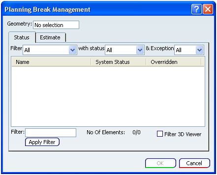
Geometry
Select a geometry to define the physical boundary of the design unit.
A selection is also highlighted in the graphics area and also in the specification tree.
Note: If you change the geometry during the design, the old planning breaks will be removed. A message will appear listing the impact of replacing the old geometry by a new.
![]()
Status
After selecting the geometry, a list of all the structural objects gets displayed in the Name column of the Status tab. The System Status column displays the current status of the object with respect to the selected geometry. You can change the status of the objects using the contextual commands.
- OUT: Sets the object to be outside a design unit.
Note: The object is listed under the Excluded Element node in the specification tree.
- IN with Planning Break: Sets the object to be inside a design unit with planning breaks.
- If the status of the object is ACROSS, then it indicated that the planning breaks are defined for the proxy.
- If the status of the object is OUT or IN, then it indicated that the planning break is not defined for the proxy. However, you can define them explicitly.
Note: If the status of the object is OUT, then it will be listed under the Excluded Element node in the specification tree. If the status of the object is IN, then it will be listed under the Included Element node in the specification tree.
- IN fully included: Sets the object inside a design unit. The proxy has no planning break defined whatever is its status.
- Reset to system status: Removes all exceptions on this object. The proxy and its planning breaks are removed from the exception management.
- In addition, other commands available are:
- Center graph
- Reframe On
- Hide/Show.
The change status gets displayed in the Overridden column.
Tips:
|
You can filter the object displayed for the ease of selection.
- Filter
- Select the appropriate type of structural object in the Filter list.
You can select:
- All: Displays all type of structural objects.
- Panel: Filters all panels.
- Stiffener: Filters all stiffeners.
- Beam: Filters all beams.
- status
- Select the appropriate type of status in the status list.
You can select:
- All: Displays all objects.
- OUT: Filters all objects with OUT status.
- IN: Filters all objects with IN status.
- ACROSS: Filters all objects with ACROSS status.
- Exception
- Select the appropriate type of exception from the Exception list.
You can select:
- All: Displays all objects.
- OUT: Filters all objects with OUT exception.
- IN: Filters all objects with IN exception.
- PB: Filters all objects with PB exception.
- (Blanks): Filters all objects having no exception.
- Filter
- In the Filter box, you can key-in alpha numeric query for filtering. It is used to sub filter the above query results.
Note: This filter is case sensitive.
- No Of Elements
- The No Of Elements displays the count of total number of objects filtered to total number of objects available for filtering.
- Filter 3D Viewer
- Select the Filter 3D Viewer check box to see the filter result in the graphic area.
![]()
Estimate
The Estimate tab contains the following options:
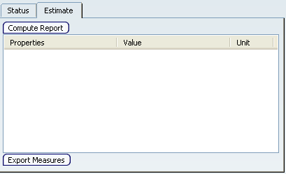
- Compute Report
- Click
Compute Report to generate a report.
The computed weight and the COG values are displayed in the area below.
Notes:
- While computing the report all the objects referred by the design unit are considered.
- You can set the unit for weight and COG at Tools > Option > General > Parameter and Measure > Units tab. For more information, refer to Infrastructure User's Guide.
- Export Measures
Click Export Measure to make all properties persistent in the representation of the design unit. Also a geometrical point is created at the location of the COG.
Note: Each time Export Measure is clicked, a point is created.