Calculating Weight and Center of Gravity | ||||||
|
| |||||
Click Planning Break
 in the Operation toolbar.
The Planning Break Management dialog box appears.
The selected design unit is displayed in the Geometry box. All the structural objects along with their system status are listed in the Status tab.
Click Compute Report.
The values of weight and COG coordinates in the X, Y and Z direction are displayed in the area below.
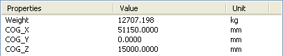
Tip: The units for displaying the weight and COG can be set at Tools > Option > General > Parameter and Measure > Units tab.
The COG is placed in the model and also a new node appears in the specification tree below the GeometricalSet_PB node.
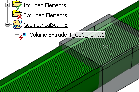
Note: If you click Export Measures number of times, then number of COGs will be created at the same location in the graphics area. Also, number of new nodes will be created in the specification tree below the GeometricalSet_PB node.