Stiffener Dialog Box | ||||
|
| |||
Category
Select the appropriate category from the Category list.
To select the category defined in the Project Dictionary Resource set in Project Resource Management, select the More in the Category list. The Types Browser Dialog Box appears.
![]()
Name
The name is assigned automatically, using the object naming rules. If you want to assign a specific name, clear the Automatic check box and type the name in the Name box.
![]()
Fast Preview
Select the Fast Preview check box to get a quick preview of all the operations performed for creating the stiffener. It displays a trace of the stiffener in your 3D session. When this check box is selected, the display of the stiffeners is optimized during any operations performed in the Stiffener dialog box as it generates only a trace and not the full presentation of the stiffener.
When the Fast Preview check box is cleared or when you click OK, both the trace and the full presentation of the stiffener is generated.
![]()
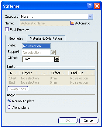
Geometry
- Plate
-
Select a plate in your 3D session and it appears in the Plate box.
Selections made for plate should be compatible with the category selected.
- Support
-
Selections made for support should be compatible with the
category selected.
Select a support in your 3D session and it appears in the Support box. To select the support:
- A plane
- A surface that intersects the plate. You can create your own surface if you need to
- A grid
The stiffener is placed when you select a support. The support defines a trace on the plate that the stiffener follows when it is placed.
You can also select a support as follows:
- Select a plane in 3D session.
- Right-click the Support box, and choose Select Reference Plane to select a plane from predefined plane system.
Note: You can create a new plane to define the support using the Create Plane option.
- Click the
 button next to the Support box to display the elements list. From the displayed list, select the support. You can use the Remove and Replace commands to remove and replace the selected reference respectively.
- Offset
- In the Offset box, type the value or use the arrows to change the value, by which the stiffener should be offset from the support you have selected. The value is expressed in the units selected in your workbench.
If you want the offset in reverse direction, use a negative sign in the offset value.
- Limits
- The Limits area displays the limits of the stiffener. By default, stiffeners are placed from end to end on the selected plate.
You can select:
- Geometrical entity
- Structural object
In the Name box, select Start and select a starting limit. You can select a plane, plate, another stiffener or a surface. The stiffener is limited as soon as you make your selection.
Similarly, select end.
In the Offset box, you can define the offset value of each stiffener limit.
Note: You can select a volume or a closed surface as the limiting element. In this case the Offset box is unavailable.
You can swap the default limits by clicking the Swap Ends button.
You can define the stiffener limits. However, the Swap Ends button becomes unavailable once you define the limit.
- Angle
- You can select the angle at which a stiffener is placed. By default, the Normal to plate option is selected. To place the stiffener along the selected support, select the Along plane option.
![]()
Material And Orientation
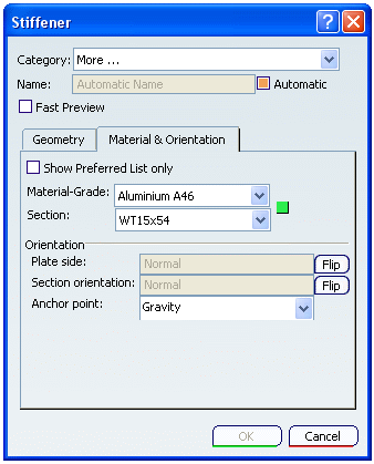
- Show Preferred List only
- Select this check box to show only recommended combination of material-grade and thickness.
Note: If the Material Table is not set in the Project Resource Management, then this option is unavailable.
- Material-Grade
- Select a material-grade from the Material-Grade list. Once you select a material, valid grades are available for selection.
- Section
- Select a section in the Section list. A section is pre-selected based on your previous session. If you select More... in the list, then the Table Browser dialog box appears.
Note: The previously selected 10 sections are displayed in the Section list for quick selection.
Tip:
If the Material Table is set in the Project Resource Management, then a  or or  or or  will appear next to the Material-Grade and Section box. will appear next to the Material-Grade and Section box.This symbol indicates if the selected combination of material-grade and section is recommended or not.
|
| Important: If the Material Table is not set in the Project Resource Management, then you can select material-grade and section from the database. |
- Plate Side
- By default one side of the plate is selected to place the stiffener. Click Flip to place the stiffener on the other side of the plate.
- Section Orientation
- At the start, the stiffener is placed with the default orientation. Click Flip to toggle the orientation.
- Anchor Point
- Select the appropriate anchor point from the Anchor Point list to get the correct orientation of the stiffener.