Molded Conventions | ||||||
|
| |||||
Overview
This section provides a brief overview of the molded convention resource file.
Plates and stiffeners are oriented according to their location in the hull and with respect to the midship or centerline. Midship and centerline definitions are specified in XML file describing reference plane system.
The following image depicts a sample xml file.
| Important: Conventions are specified for each object class of plates and stiffeners defined in the feature dictionary. |
| Tip: The sample MoldedConventions.xml file is located at ...\startup\EquipmentAndSystems\Structure\Project\ShipBuilding_Hull1234. |
![]()
Customization of Molded Conventions
When customizing the xml do not change the format of the xml.
Stiffeners
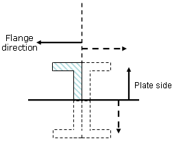
- PlateSideOrient
- The side of the plate on which the stiffener is placed .
- SectionOrient
- Orientation of the stiffener flange.
- AnchorPoint
- The point at which the stiffener section is anchored along its trace.
Stiffeners on Free Edge
- AnchorPoint
- The point at which the stiffener section is anchored along its trace.
Symbols Used
The following is a list of orientations that can be used to specify molded conventions.
Symbols used for orientations (ThicknessOrient of plates, PlateSideOrient and SectionOrient of stiffeners).
- HP
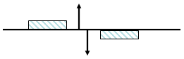
- Horizontal plus. Nls name : Top.
- HM
- Horizontal minus. Nls name : Bottom.
- LP
- Longitudinal plus. Nls name:
- Portside, if FrontOrientation = Xp in the project parameters file (Front of the ship correspond to X+ ).
- Starboard, if FrontOrientation = Xm in the project parameters file (Front of the ship correspond to X- ) .
- LM
- Longitudinal minus. Nls name:
- Starboard, if FrontOrientation = Xp in project parameters file.
- Portside, if FrontOrientation = Xm in project parameters file.
- LI
- Longitudinal inboard. Nls name: Inboard.
- LO
- Longitudinal outboard. Nls name: Outboard.
- NR
- Normal of support plane.
- IV
- Inverted normal of support plane.
- TP
- Transversal plus. Nls name:
- Fore, if FrontOrientation = Xp in project parameters file.
- Aft, if FrontOrientation = Xm in project parameters file.
- TM
- Transversal minus. Nls name:
- Aft, if FrontOrientation = Xp in project parameters file.
- Fore, if FrontOrientation = Xm in project parameters file.
- TI
- Transversal inboard. Nls name: Inboard
- TO
- Transversal outboard. Nls name: Outboard
- OtherI
- Other Inboard. Nls name:
- Inboard for shell plates or shell stiffeners
- Normal for plates using Other category (this orientation corresponds to the normal vector of the support used to create the plate)
- OtherO
- Other outboard. Nls name:
- Outboard for shell plates or shell stiffeners
- Invert for plates using Other category (opposite of the normal vector)
Anchor Point Definition
- StiffenerClass Name
- The name of the object.
- DefaultAnchorPoint
- The default anchor point you get when placing the object.
- AnchorPoint Name
- The anchor points that are available in the Anchor Point box in various dialog boxes. Each anchor point should be entered on a separate line, as shown below.
Following are the values that can be used to define DefaultAnchorPoint and AnchorPoint Name:
- catStrBottomLeft
- catStrBottomCenter
- catStrBottomRight
- catStrCenterLeft
- catStrCenterCenter
- catStrCenterRight
- catStrTopLeft
- catStrTopCenter
- catStrTopRight
- catStrGravity
- catStrWebSideLeft
- catStrWebSideRight
- catStrWebCenter
- catStrWebCenterLeft
- catStrWebCenterRight
2D View Orientation
- Orient2D_U
- Orientation in the U direction.
- Orient2D_V
- Orientation in the V direction.
The valid values you can enter are as follows:
- XP
- X plus
- XM
- X minus
- YP
- Y plus
- YM
- Y minus
- ZP
- Z plus
- ZM
- Z minus
- NA
- Not applicable (orientation attribute ignored. Example, orientation does not apply to shell plates.)