Creating a Logical System | |||||||
|
| ||||||
Select Start
 > Infrastructure > VPM Functional Logical Editor to enter the
VPM Functional Logical Editor workbench.
The RFPL specification tree appears on the left hand side of your screen.
Create a logical reference:
- Select Logical in the specification tree and click Insert a New Reference
 in the RFLP General Commands toolbar.
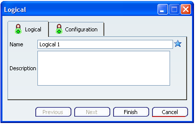
The Logical dialog box appears.

Note: You can specify the name of the system and enter a description in the Name and Description boxes respectively.
- Click Finish.
The Logical 1 node is created under the Logical node in the specification tree.
For more information, refer to VPM Functional Logical Editor User's Guide: Functional and Logical Definition: Insertion: Inserting New Reference.
- Select Logical in the specification tree and click Insert a New Reference
Create a physical reference:
- Select Physical in the specification tree and click Insert a New Reference
 .
.
The Insert - Step 1 - Product dialog box appears.
- Select Product and click Next.
The Product / Product DS dialog box appears.
Note: You can specify the necessary details about the system in the respective boxes in this dialog box.
- Enter the necessary details and click Finish.
Product x node is created under the Physical node in the specification tree.
- Select Physical in the specification tree and click Insert a New Reference
Create an implement relation:
- Double-click Logical 1 in the specification tree to activate it.
- Click Create an Implement Relation
 in the RFLP Implement Links toolbar and select
Product x in the specification tree.
in the RFLP Implement Links toolbar and select
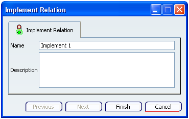
Product x in the specification tree.The Implement Relation dialog box appears.

Note: You can specify the name and enter the description in the Name and Description boxes respectively.
- Click Finish.
The implement link is created between the logical and physical roots.
The Implement Relations node with Implement 1 sub-node is created under the Physical node in the specification tree.
For more information, refer to VPM Functional Logical Editor User's Guide: Implement: Creating Implement Relations.
Create a logical port:
- Click Create New Logical Port
 in the RFLP Logical Commands toolbar and select Logical 1 in the specification tree.
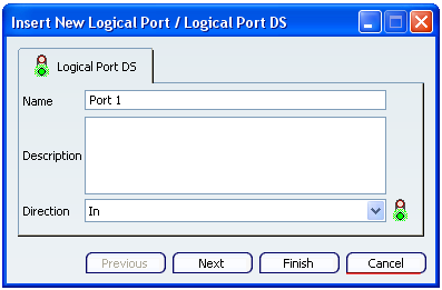
The Insert New Logical Port / Logical Port DS dialog box appears.

- Enter the name and description in the Name and Description boxes respectively and select direction in the Direction list.
- Click Finish.
A logical port is created, represented by a triangle in the graphic area.
The Ports node is added in the specification tree under Logical node.
For more information, refer to VPM Functional Logical Editor User's Guide: Functional and Logical Definition: Logical: Creating Logical Ports.
- Click Create New Logical Port
Create another logical reference with logical port in out direction.
Create a logical connection:
- Click Create New Logical Connection
 in the RFLP Logical commands toolbar and select a logical port.
 - Select second logical port.
The System Type Association dialog box appears.
- Select the system type to associate and click Next.
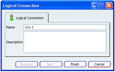
The Logical Connection dialog box appears.

Note: You can specify the name and enter the description in the Name and Description boxes respectively.
- Click Finish.
The logical connection is created.

The Connections node with Cnx 1 sub-node is created under the Logical node in the specification tree.
For more information, refer to VPM Functional Logical Editor User's Guide: Functional and Logical Definition: Logical: Creating Logical Connections.
- Click Create New Logical Connection