Defining a Piping Component | |||||
|
| ||||
Select the reference object to be defined as a piping component in the specification tree or in the graphic area.
The Piping Extension dialog box appears.
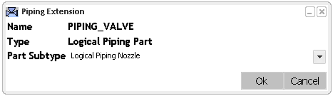
The Name box indicates the name specified by you for the reference object.
The Type box indicates the type of the part (Logical Piping Part).
Note: The Name and the Type boxes are not editable in this dialog box.
Click OK.
The reference object is defined as logical piping part.
A confirmation message showing the count of successfully defined reference objects out of total selected objects is displayed at the upper right corner of your screen.
You can notice in the specification tree that the icon has changed to
 indicating it as a piping part.
Also, a Piping tab is created in the Properties dialog box displaying the logical piping part extension.
Optional: To check the properties, right-click the reference object and select Properties.
The Properties dialog box appears.

You can modify the subtype and the attribute values by selecting it from the respected lists. To inherit the attributes value from the line ID, use the Transfer Line ID command. For more information, refer to Transferring a Line ID.
 in the
Notes:
- You can define multiple objects as the piping part at a time.
- In case of multiple selections, if some of the selected parts are already defined as the piping parts, then only non-defined parts will be recognized as the logical piping part. The count is displayed in the confirmation message that appears after clicking OK at the upper right corner of your screen.