Tips for Creating Draft Features | |||||||
|
| ||||||
Choosing the Pulling Direction
This section provides information on the pulling direction selected for creating draft features.
If you need to draft several faces using a pulling direction normal to the neutral element, keep in mind the following operating mode that will facilitate your design:
- Click
 and first select the neutral element of your choice. The pulling
direction that appears is then normal to the neutral element.
Select the face to be drafted and click OK to create
your first draft.
 - Now, to create the other drafts in the same 3D shape, note that by default the application uses the same pulling direction as the one specified for creating your first draft. As designers usually use a unique pulling direction, you do not need to redefine your pulling direction.
![]()
Deactivate and Extract Geometry Commands
If you perform a difficult draft operation, for example resulting in twisted faces, you can use the Deactivate and Extract Geometry commands to solve your difficulties.
The Extract capability lets you generate separate elements from the initial geometry, without deleting the geometry.
When the application informs you via an error message window that your operation cannot be properly performed, closing the window displays a new dialog box providing you with a solution: you can deactivate the feature and extract its geometry.
After clicking Yes to confirm these operations, the feature appears as deactivated in the specification tree. A node Extracted Geometry (Feature.1) is displayed in the tree too.
![]()
How to Avoid Draft Skin Faces that Intersect?
This section provides workarounds to avoid intersecting draft skin faces.
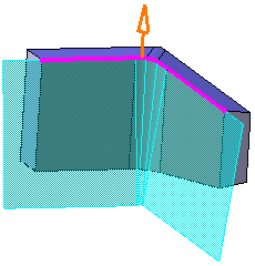
When performing a basic draft feature, the preview shows that the
draft skin faces intersect.
Workarounds
There are two possible workarounds to obtain a satisfactory result:
Workaround 1:
Use Variable Angle Draft ![]() , which allows you to assign different angle values.
, which allows you to assign different angle values.
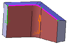 |
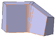 |
| Preview | Result |
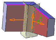
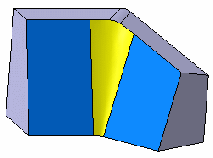
Workaround 2:
Define limiting elements (for example two planes as shown below)
and fulfill the gap with a Fill ![]() or
Multi-sections Surface
or
Multi-sections Surface ![]() feature (a Generative Shape Design
license is required to use these capabilities):
feature (a Generative Shape Design
license is required to use these capabilities):
 |
 |
| Preview | Result |
For more information, see Creating Variable Angle Drafts.
![]()
How to Add and Remove Material at the Same Time?
This section provides workarounds to add and remove material at the same time.
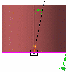
You perform a neutral draft operation on a simple pad. Because the chosen pulling direction is not normal to the neutral element, the application both needs to remove material from one 3D shape area, and add material to another area of the shape.
Complete cylinder: the draft angle is less than angle between
pulling direction and cylinder axis
.
The previews shows that the draft skin adds and removes material.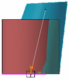
Workarounds
There are three possible workarounds to obtain a satisfactory result.
Workaround 1:
If possible, change the pulling direction so that material is either added or removed throughout.
Workaround 2:
Increase the draft angle value so that material is either added or
removed throughout. (e.g. in above case increase angle from 5 deg.
to 15 deg., leads to uniform removal of material). In general for
cylinders magnitude of draft angle should be greater than angle
between pulling direction and cylinder axis, for this to happen.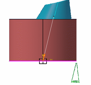
Workaround 3:
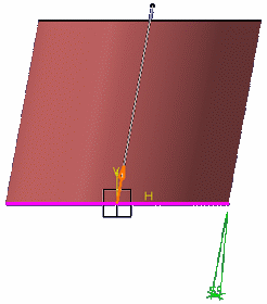
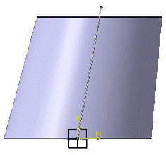
Prior to using Draft Angle ![]() , when defining
the pad's direction select the same geometrical element as the one
you will use for defining the pulling direction. Then draft the
faces you want
.
, when defining
the pad's direction select the same geometrical element as the one
you will use for defining the pulling direction. Then draft the
faces you want
.
![]()
How to Avoid Too Large Draft Skins?
This section provides workarounds to avoid extra large draft skins.
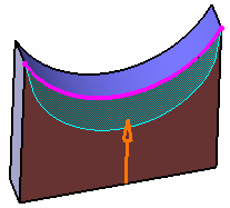
You entered a large draft angle value. Previewing the feature shows
that the draft skin is too large.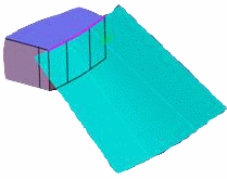
The application issues an error message. Clicking on this message
shows that a relimitation track is not long enough. This indicates
that the corresponding red relimitation surface has not been
extrapolated enough.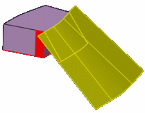
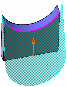
The extrapolation of the relimitation surface is deliberately
limited so as not to go beyond a computed 3D box. Most often,
industrial draft angle values are relatively small so that
extrapolating surfaces very far is not necessary.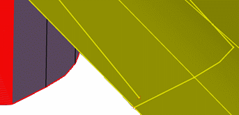
Workarounds
There are two possible workarounds to obtain a satisfactory result :
Workaround 1:
Either use the draft skin generated by the failed draft variable draft -for this, confirm the use of the Extract capability as proposed by the application)...
Workaround 2:
Generate and extrapolate a draft skin using Swept
Surface ![]() (a
Generative Shape Design license is required to use
this capability)
(a
Generative Shape Design license is required to use
this capability)
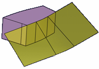
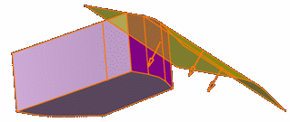
and sew it onto the initial body using Replace Face ![]() or Sew Surface
or Sew Surface ![]() :
:
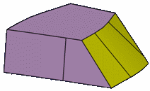
![]()
How to Draft Faces Separated by a Concave Edge?
This section provides workaround to draft the faces separated by a concave edge.
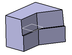
You draft faces using a parting element located above the neutral element and you use a positive angle value.
Additionally, the faces to be drafted are separated by a concave edge as shown by the white arrow .
An error message is issued. The application cannot compute the
draft feature, even if you try to perform two draft operations.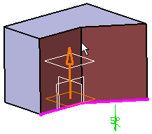
Workaround
Perform a Split operation and then draft the faces you want. To be
more precise:
- Split
 the 3D shape you want to draft and keep the upper
portion of it.
 - Draft this portion without using any parting element.
- Create a new body, then copy and paste the initial 3D shape into it.
- Split this body using the direction opposite to the one used for the first split operation.
- Assemble
 this body to the upper 3D shape.