Creating Basic Draft Features | |||||
|
| ||||
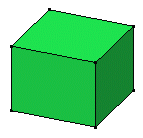
The Draft Definition dialog box opens and an arrow appears on a plane, indicating the default pulling direction. Constant Angle Draft
 is activated.
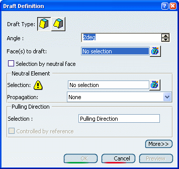
There are two ways of specifying the face to be drafted: either explicitly, or by selecting Selection by neutral face. For the purposes of our scenario, check Selection by neutral face.
Select the upper face as the neutral element. This selection allows the application to detect the face to be drafted.
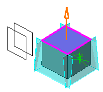
The neutral element is now displayed in blue, the neutral curve is in pink. The faces to be drafted are in dark red.
The pulling direction is now displayed on top of the part. It is normal to the neutral face.
The Controlled by reference option is now activated, meaning that whenever you will edit the element defining the pulling direction, you will modify the draft accordingly.
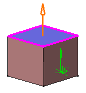
The default angle value is 5. Enter 7 degrees as the new angle value. The application displays the new angle value in the geometry.
Optional: Click Preview to see the draft to be created.
The previewed draft appears in blue.
Click More>> to access additional options.
Select Plane.1 as the limiting element.
The arrow points to the portion of material to be kept to perform the operation.
Warning: Always ensure that limiting elements intersect neutral curves. If not, the application does not trim draft features. 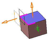
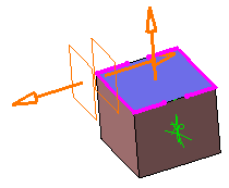
Select Plane.2 as the second limiting element.
Note that the number of limiting elements you select is indicated in the dialog box, just in front of the Limiting Elements box.
Click the arrow to reverse its direction, and therefore retain the opposite side of the feature.
Click OK to confirm the operation.
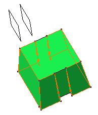
The faces are drafted but the part areas included between both limiting planes have not been modified, as specified through the limiting element option.
Warning: In some cases, you can only select a group of faces generated by the draft and not one particular face of the draft. It happens when you create a pad, add a draft on it and then add another draft that is based on the face of the pad. 