Creating Advanced Drafts

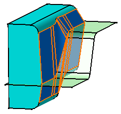
You can draft basic 3D shapes or create drafts from reflect lines using Advanced Draft command. This command also helps you to specify two different angle values for drafting complex shapes.

We recommend the use of this command to users already familiar with draft capabilities.

This task shows you how to draft two faces with reflect lines, and this by specifying two different angle values and by using both modes available.

Related Topics
Creating Advanced Drafts: About Parting Line Adjustment
About Creating Draft Features
More about Advanced Drafts

Use the Independent Option

You need to specify two angle values for creating an advanced draft using Independent option.

  1. Select View > Toolbars > Advanced Dress-Up Features to access the Advanced Dress-Up toolbar.

  2. Click Advanced Draft .

    The Draft Definition (Advanced) dialog box appears and you can see a default pulling direction (xy plane) in the geometry.
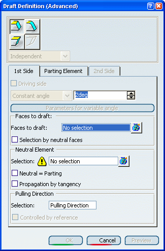
  3. Specify that you wish to draft two faces with reflect lines by clicking both icons as shown:


    The combo list below is now available.

  4. For the purposes of our scenario, ensure that Independent is on.

  5. In the Neutral Element frame, click No Selection and select the fillet as shown.
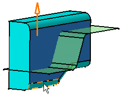


  6. In the Pulling Direction frame, click Pulling Direction in the Selection box and select the part's bottom face to specify a new pulling direction.

  7. Enter 10 as the angle value.

  8. Click the Parting Element tab to define the parting element.
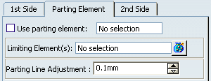


  9. Select the Use parting element check box and select the green surface as the parting element.

    The Parting Line Adjustment option adjusts the smoothness of the transition zone on the draft surface. Usually, the default value (0.1mm) proves to be efficient most of the time.

  10. Click the 2nd Side tab to define the second face to be drafted.

  11. In the Neutral Element frame, click No Selection from the combo list and select the second fillet.

    Both faces to be drafted are now selected. The application displays the reflect line in pink.
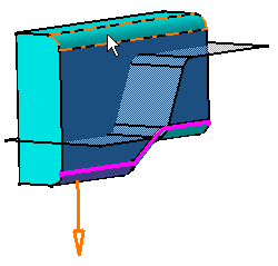


  12. Enter 6 as the angle value.

  13. Click OK to confirm.

    Both faces are drafted using a distinct angle value, as specified.
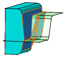


    Due to the use of the angle values you have set, this operation results in a "step" where both drafted faces meet.

Use the Driving/Driven Option

You can create an advanced draft using Driving/Driven option. In this case, the angle value you specify for one face affects the angle value of the second face.

To avoid the previous result, you can use the Driving/Driven option as explained hereafter.

  1. Double-click Draft.1 in the specification tree to edit it.

    The Advanced Draft dialog box appears.

  2. Set Driving/Driven.

    You can note that the Driving side option is checked, meaning that the angle value you specified for the first face you selected (10 degrees) is the driving value.

  3. If you click the 2nd Side tab, you can notice that the angle value box is no longer available. In concrete terms, the application will compute the value for the second face so as to avoid the "step effect".

  4. Click OK to confirm the operation. The application has adjusted the second drafted face.


Tips:
  • If you prefer to set the angle value you specified for the second face you selected (6 degrees) as the driving value, just click the 2nd Side tab and select the Driving side check box.
  • Sometimes, some resulting faces of the "Driven draft" are not apt for being removed from molds. In this case, we recommend you to check this using the draft analysis capability. For more information, see FreeStyle Shaper Optimizer & Profiler User's Guide: Analyzing Shapes: Analyzing Draft Angle.