Setting Up Environment for Multi-Turret Lathe Machining | ||||
|
| |||
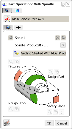
Double-click Part Operation in the Activities Process Tree.
Set the following parameters on the Part Operation dialog box.
- reference machining axis system
- design part and stock, which allows material removal simulation later.
Click Create a Generic Machine
 .
.The Generic Machine dialog box appears.
Click Mill-Turn Machine
 to initialize the machine parameters.
Select the Spindle tab.
 By default,
the reference machining axis system defined on the
Part Operation is assigned to the spindle.
By default,
the tool path points shown in Tool Path Replay dialog box and APT output are with respect to Part Operation axis system in spindle plane. You can also show tool path points shown in Tool Path Replay dialog box and APT output with respect to turret axis system. For more information, please refer to the Tool Path Points Based on Turret.
By default,
the reference machining axis system defined on the
Part Operation is assigned to the spindle.
By default,
the tool path points shown in Tool Path Replay dialog box and APT output are with respect to Part Operation axis system in spindle plane. You can also show tool path points shown in Tool Path Replay dialog box and APT output with respect to turret axis system. For more information, please refer to the Tool Path Points Based on Turret.Note: When the spindle is selected in the Spindles list, the corresponding spindle and the associated spindle axis system are highlighted in the 3D view. See 3D Feature for Spindles
Select the Turret tab.
- Set the turret name to Upper Turret

Note: When the turret is selected in the turret list of Turrets, the corresponding turret and the associated turret axis system are highlighted in the authoring window. See 3D Feature for Turrets
Make sure that the Manufacturing Program called PGM UT is defined on this turret.
- Click Turning Tool Axis System
 and select an appropriate axis system in the authoring window
to assign it to the lower turret.
and select an appropriate axis system in the authoring window
to assign it to the lower turret. - Set Turning Tool Axis System, Axial and Radial axes, and Tool Change Point parameters.
Make sure that the Manufacturing Program called PGM LT is defined on this turret.
- Set the turret name to Upper Turret