About Multi-Slide Lathe Machine | ||||
|
| |||
Spindle Definition
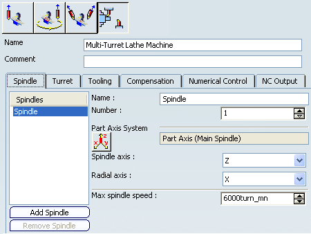
When you select the Spindle tab in Generic Machine dialog box, the following dialog box appears.
- On the left, there is a list of spindles with Add/Remove buttons to add or remove these entities.
- On the right, properties of the selected spindle are displayed.
- Name
- Each spindle has a name. When there is more than one spindle defined on
the machine then spindle name is displayed at the bottom of Machining Operation
dialog box.
 By default,
single spindle is used and is output
in APT in place of MFG_SPINDLE_NAME.
 - Number
- Each spindle has a number, which is written in valuated in APT in place of MFG_SPINDLE_NUMBER. Spindle name and number can be valuated in NC_MACHINING_AXIS and NC_ACTIVITY_HEADER syntaxes.
- Part Axis System
- Part Axis System defines the plane where Tool Path Replay, and time based replay are represented.
- Spindle Axis
- Specifies the spindle axis.
- Radial Axis
- Specifies the radial axis.
- Max Spindle Speed
- Specifies the maximum spindle speed.
![]()
Counter Spindle Output
Counter spindle output is managed by the Use Spindle Axis system defined in the Machining Operation check box in the Option tab of the Part Operation dialog box. This is for a Multi-slide lathe machine or a Mill-Turn machine. See Creating a Part Operation
Note: To get the tool path points with respect to Counter Spindle Part axis system you must have a machining axis system on the Counter Spindle Part axis system.
The Use Spindle Axis system defined in the Machining Operation check box provides tool path points or coordinates of the tool positions of the tool path for Machining Operations defined on the counter spindle with respect to Counter Spindle Part axis system. Machining axis change definition is avoided.
Here is a view of the Multi-Slide Lathe Machine setup showing main and counter spindles:
If a program is defined with a Machining Operation on the main spindle, and a second Machining Operation on the counter spindle, here is a typical replay of the Machining Operation defined on the counter spindle:
Sample of the APT output obtained for the program:
Some counter spindle capabilities are:
- Counter Spindle can be defined at any angle to Main Spindle axis.
- The tool path on the counter spindle is in the turret plane, even if the Counter Spindle Part axis system is rotated by an angle (that is, if the counter spindle plane is not at zero degrees).
![]()
Turret Definition
When you select the Turret tab in Generic Machine dialog box, the following dialog box appears.
- On the left, there is a list of turrets with Add/Remove buttons to add or remove these entities.
- On the right, properties of the selected turret are displayed.
- Name
- Each turret has a name, which is displayed in the Activities Process Tree next to the Manufacturing Program with which it is associated. See Assigning Manufacturing Programs to the Turrets
- Number
- Each turret has a number, which is output in APT output in place of MFG_CHANNEL_NUMBER in the program header or synchronization syntax.
- Type
Turret Type defines the turret type as:
- Rotary Turret
- Mill Turret, turret that has B-axis capability
 By default,
the turret type is set to Rotary, whenever you assign a machine to part operation.
By default,
the turret type is set to Rotary, whenever you assign a machine to part operation.This is done to maintain compatibility with the previous version because if the turret type is changed automatically from Rotary to Mill then the APT source can contain B-axis and C-axis information. Moreover, Tool Path Replay and simulation can also consider the B and C axes (which is not useful if you do not want to use that functionality) and use the Setup angle to simulate the B-axis.
- Turning Tool Axis System
- Specifies the Turning Tool Axis System by clicking
 .
. - Tool Change point
- Tool Change point can be defined manually through its absolute coordinates (X,Y,Z). Since this point might be considered as the origin of the Turning Tool Axis System, you can use the button at the bottom of the Generic Machine dialog box to automatically set it.


