Displaying Views | ||||||
|
| |||||
Track History of View Display
You can track history of view display in the current working session using a specific setting.
Select the Track history of view display check box.
From now on, once they have been displayed, views will be identified in the specification tree using a light purple background.
Note: Already-displayed views will remain identified using the light purple background within the current working session, even if you deactive the setting later on.
Views that have not been displayed yet are identified in the specification tree using a transparent background.
Note: Refer to Display for more information.
![]()
Display Views
You can set up the optimal context for checking views.
Select Display View.
- The selected view is displayed in the most appropriate way according to the context. In the 3D window, a number of elements are either shown (the view, its sheet and layout) or hidden (other views of the sheet, other sheets) as necessary. In the 2D window, the selected view and the sheet containing it are activated if necessary.
Note: Active views are identified in the specification tree using a light blue background. Note that the "active view" status has priority over the "already-displayed view" status.
- A reframe is performed on the view display area. This display area is either the default one, or a custom one. Refer to Displaying Views and Displaying Views for more information.
Note: The default reframe does not take into account the 2D elements in the view background.
- The Cutting Plane
 and Display Backgrounds as Specified for
Each View
and Display Backgrounds as Specified for
Each View
 options are activated in the Visualization toolbar.
 - If Track history of view display is selected, the selected view is identified as displayed in the current working session and the color of the view item is modified accordingly in the specification tree.
Tip: If you are working in the 2D window of 2D Layout for 3D Design, you can also right-click the view and select . In this case, the view will be displayed in the 3D window. - The selected view is displayed in the most appropriate way according to the context. In the 3D window, a number of elements are either shown (the view, its sheet and layout) or hidden (other views of the sheet, other sheets) as necessary. In the 2D window, the selected view and the sheet containing it are activated if necessary.
| Important: You can remove the color code used to identified already-displayed views from the specification tree. To do this, right-click the layout and select Delete History of Displayed Views. |
![]()
Capture the Display Area
By default, the view display area contains the content of the view and of its background. You can define your own custom display area, which will be taken into account when displaying the view.
Perform the previous scenario, and display the view as you want to capture it.
| Important: You can remove a view's custom display area by right-clicking the view and selecting . The display area for this view will now be the default one. |
![]()
Edit the Display Area
You can edit a view's default or custom display area.
Select .
A reframe is performed on the default view display area. A white frame appears, symbolizing the display area. The area outside of the display area turns semi-transparent.
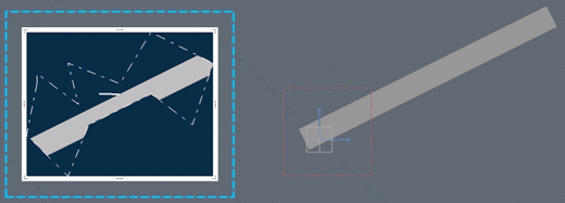
Modify the display area according to your design's needs.
- To move the display area, drag the white frame or the transparent area.
- To resize the display area, drag the corner
 or middle handles
  of the white frame.
Tips: - By default, the display area is snapped on the grid. You can deactivate snapping temporarily by pressing Shift while moving or resizing.
- By default, when resizing the display area, only the manipulated handle moves. You can also move the opposite handle by pressing Ctrl.