More About Sections/Auxiliary Views | |||||||
|
| ||||||
General Remarks
This sub-topic provides general remarks about sections and auxiliary views.
Section views, section cuts or auxiliary views are created using an existing 2D profile (a single line or a multi-segment profile) in the active view. Such views are based on a plane perpendicular to the active view which contains the directional element (the selected line). The projection direction depends on two factors:
- The cursor location.
- The projection method. For more information, refer to About the Projection Methods.
Once created, the new view is not associative to the directional element, and this element is not transformed into a callout. Therefore, it is impossible to edit section profiles after the view has been created.
Section views, section cuts or auxiliary views are positioned according to their reference view. Therefore, moving a reference view also moves its linked views.
![]()
Section/Auxiliary View Origin Point
This sub-topic provides information about the origin point of sections and auxiliary views.
The section/auxiliary view origin point is a 3D projection of the active view origin point to the geometry used as a cutting profile.
See the illustrations below:
The Front view origin point (represented in red) is a projection of the 3D axis origin (in blue). For more information, you can refer to About View Creation and Layout Views Customization.
Front view:
3D view: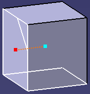
The slanting line is used as a cutting profile to create a Section view. The Front view origin point is projected to the cutting profile to create the Section view origin point (in green).
Front view: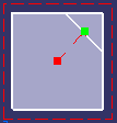
Section in 3D view: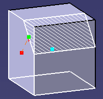
You can see that the section view origin point (in green) is not a projection of the 3D axis origin (in blue), but a projection of the active view origin point (red).
![]()
Section/Auxiliary View Axis Orientation
This sub-topic provides information about the orientation of sections and auxiliary views axes.
The section/auxiliary view axis orientation is based on the cutting profile angle defined in the primary view. In this way, the section/auxiliary view axis follows the projected element plane, in order to simplify the design work.
See the illustrations below:
Front view axis orientation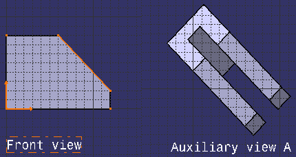
Auxiliary view axis orientation (angle = 45deg)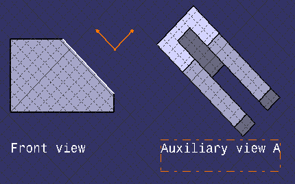
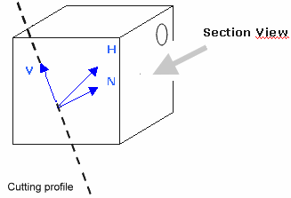
More precisely, here are the rules used to position the H / V / N axis orientation in an auxiliary/section view:
- H = has the same axis and the inverse direction of the active view N axis. (As the reference view N axis is always going out of the geometry, so the auxiliary/section view H axis is going inside the geometry).
- V = has the same axis as the cutting profile. Its direction depends on N and H: these three directions must form a direct trihedron (right-handed cartesian system).
- N = the axis is the chosen point of view (the user's look), the direction is toward the user.
As N is fixed and H is known, V is deduced.
See illustrations below:
Active view axis orientation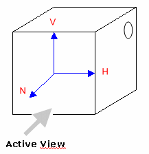
Section/Auxiliary view axis orientation