About the Generation of Drawings or Views from 3D | |||||
|
| ||||
Support of 3D Shapes
This sub-topic discusses the support of 3D shapes when generating drawings or views from 3D.
You can generate a drawing (or a view from 3D) from the 2D layout representation of a 3D shape:
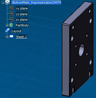
Projection views of the 3D shape are defined in the 2D Layout for 3D Design window:
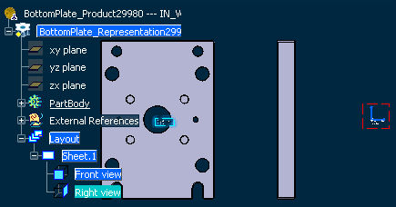
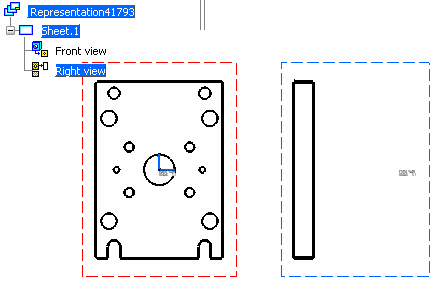
The 3D shape is projected in the resulting drawing representation:
![]()
Support of Assemblies
This sub-topic discusses the support of assemblies when generating drawings or views from 3D.
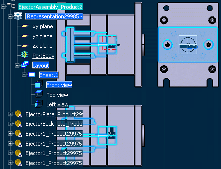
You can also generate a drawing (or a view from 3D) from the 2D layout representation of an assembly:
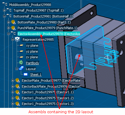
The 2D layout representation of the assembly and its context are shown in the 2D Layout for 3D Design window:
The 2D layout assembly is projected in the resulting drawing representation:
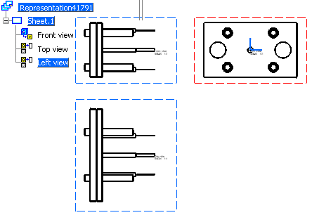
Note that only the 2D layout representations that are loaded in the current session can be projected. If part of an assembly is not loaded, then it will not be projected in the drawing.
![]()
Miscellaneous Remarks Regarding the Generation of Drawings or Views from 3D
This sub-topic discusses miscellaneous points about the generation of drawings or views from 3D.
The following sub-topics are discussed:
- 2D Components
- Associativity and Update
- Dimensions
- Geometry
- Show/No Show
- Standards
- Views
- View Callouts
- Generation of Drawings or Views from 3D Using Generative View Styles
Important:
Before
you begin generating drawing or views from 3D, you need to check
that your settings are appropriate.
Go to Tools > Options > Mechanical > Drafting > View
tab, and:
|
2D Components
- 2D component references in layout detail sheets are not generated in drawings. Likewise, detail sheets are not taken into account during the generation.
- 2D component instances are generated in drawing views. They are linked to their 2D component references located in the 2D Layout. Thus, changes on a 2D component reference are reflected in the generated 2D component instance, when this one is synchronized.
- Colors of sub-elements defined in a 2D component reference are not projected in drawing views. Generated colors are based on the ones applied to the 2D component instance only.
Associativity and Update
The created drawing is associative to the layout, which means that if you modify the layout (if you add or delete annotations, dimensions or dress-up, or if you add or delete geometry for example), the drawing will usually appear as being not up-to-date and you can update it (you can update all views or a selection of views in the drawing). Furthermore, the drawing will appear as being not up-to-date after adding, deleting or modifying 3D shapes or assemblies aggregated under an assembly layout.
There are exceptions:
- if you simply modify geometry (change the coordinates, for example) or graphic properties, the drawing will not appear as being not up-to-date.
- changes to the scale, position or orientation of the layout view have no effect when updating the drawing. This lets you overload the position, scale or orientation of generated drawing views to add extra views to the drawing.
The Update icon
![]() is active in the Update toolbar to indicate a drawing or a sheet
which is not up-to-date and needs to be updated (this can be all views in
the sheet or some of them only). Update symbols also appear in the specification
tree to indicate drawings
is active in the Update toolbar to indicate a drawing or a sheet
which is not up-to-date and needs to be updated (this can be all views in
the sheet or some of them only). Update symbols also appear in the specification
tree to indicate drawings
![]() and sheets
and sheets
![]() containing views that need to be updated.
containing views that need to be updated.
- You can update all views in the active sheet by clicking Update
 .
.
- You can update all views in a given sheet (or in a selection of sheets), by selecting and right-clicking the sheet(s) and then choosing Update Selection. You can also use the same method for a drawing: this will update all sheets (and therefore all views) in the drawing.
- You can update a selection of views by selecting and right-clicking the view(s) you want to update and choosing Update Selection from the contextual menu. Only the items you select are updated.
Update symbols remain in the specification tree for the items that have not been updated, so you always know which items are up-to-date and which are not.
- Any operation (change the color, delete, move, for example) performed on drafting items generated from a layout view content is lost after an update. However, you will not be prevented from modifying these items.
- Drawing generated from 2D Layout with the Activate 2D visualization mode (Right-click a view, select Background > Activate 2D visualization mode) option activated on a view, will have only the 2D planar elements that are in the same plane as this view. For more information, refer to Visualizing the 2D Elements.
Dimensions
- Dimensions that are generated directly from the 3D are isolated. Such dimensions are displayed by default using the dark blue color when the Activate element's analysis check-box is selected in Tools > Options > Mechanical > Drafting > Display tab.
- Generated Curvilinear and Chamfer dimensions cannot be manipulated and are seen as not-up-to-date.
- Dimensions added to generated 2D geometry (in drawing views) are not associative. Such dimensions are displayed by default using the grey color when the Activate element's analysis check-box is selected in Tools > Options > Mechanical > Drafting > Display tab.
Geometry
- Interactive geometry cannot be constrained to generated 2D geometry. Therefore, when adding interactive geometry, geometrical constraints are detected but not created, and constraint creation commands do not authorize the selection of generated 2D geometry.
- Associative position and associative orientation do not work on generated 2D geometry and generated annotations (in drawing views). Therefore, selecting such items is impossible when creating annotations.
- The generation of 2D geometry (wireframe and 2D points) is optional. You can specify whether you want to generate 2D geometry using the View from 3D > Generate 2D Geometry option available via Tools > Options > Mechanical > Drafting > View tab (this option is also accessible in the drawing via the generated view's properties: right-click the view and select Properties > View from 3D > Generate 2D Geometry).
Show/No Show
- Construction geometry and geometry which is placed in No Show space is not generated in drawing views.
- Layout elements which are hidden are not generated: this avoids overloading drawing representations with elements in No Show space.
Standards
The standard used for the drawing must be compatible with the standard used for the layout (for example, JIS for the drawing and JIS_3D for the layout).
Views
- Once created, drawing views have the same type and the same name as their original views.
- Only design views and isometric views can be generated from a layout to a drawing. Main views and background views cannot be generated. However their content is copied when creating a full drawing.
- In the Drafting workbench, it is not possible to create clipping views from drawing views that have been generated from a 2D Layout for 3D Design view.
View Callouts
2D Layout callouts are represented similar to other annotations during the creation of a drawing view from a 2D Layout view.
- The callouts are isolated (there is no link with any 2D Layout or generated view).
- Callout texts are isolated. This implies that even if the name of the generated view is changed, the callout texts will not reflect this change.
- The generated callout is deleted and recreated at every view update.
- Invalid callouts are systematically generated since they are present in the layout.
Generation of Drawings or Views from 3D Using Generative View Styles
You can generate a drawing view from a 2D Layout for 3D Design view which uses a generative view style. In this case, the generative view style is entirely managed in the 2D Layout for 3D Design view and layout.
- If the 2D Layout for 3D Design view is associated with the generative view style, then the generated view will also have the same generative view style. However, you cannot modify or delete the associated generative view style.
- Views extracted from a layout with embedded generative view styles turn to not-up-to-date in the following cases:
- when an embedded generative view style is either synchronized with its corresponding XML file, added to the layout or removed from the layout.
- when a generative view style is applied to, or removed from, any view in the layout.
![]()
Integration with Functional Tolerancing and Annotation (FTA)
This sub-topic provides information about the integratin with Functional Tolerancing and Annotation.
The following sub-topics are discussed:
- Object Generated in 2D Layout Views created from FTA
- Note Object Attributes (NOA)
- FTA Annotations: General Information
- FTA Annotations: Specific Information
- Dress-up Elements
- Constructed Geometry
Object Generated in 2D Layout Views created from FTA
In the case of 2D layout views created from FTA, the following FTA objects are generated from 2D Layout for 3D Design in a drawing or view from 3D:
- Text with Leader
- Text
- Text Parallel to Screen
- Flag Note with Leader
- Flag Note
- Datum Element
- Datum Target
- Geometrical Tolerance
- Constructed Geometry
- Roughness
- Framed (Basic) dimension
- Dimension
- Cumulated Dimension
- Stacked Dimension
- Coordinate Dimension
- Curvilinear Dimension
- Note Object Attributes
The following objects are visualized in 2DL views background, but not generated in a drawing or view from 3D:
- View Frame
- Capture Callout
- Restricted Area
- Deviation
- Correlated Deviation
- Distance Between Two Points
Note Object Attributes (NOA)
The Note Object Attributes (NOA) from 2D components behave like generated 2D instances.
-
When the orientation of the Note Object Attribute from 2D component is modified, then the text orientation, follows the text orientation reference set in the 2D component reference.
-
In FTA, this attribute has no impact on annotations since the notion of sheet does not exist. The texts contained in Note Object Attribute from 2D component always follow the NOA orientation. So it is important to set the orientation reference of texts contained in 2D component to View/2D component option in Edit > Properties > Text tab (right-click view, select Properties from contextual menu) whenever the texts orientation need to follow the NOA orientation. Refer to Text Tab for more information.

FTA Annotations: General Information
FTA annotations are generated only if they satisfy the following conditions:
-
Belong to the same 3D shape as the one containing the 2D layout view which is generated. A drawing view generated from a 2DL view never extracts the context in which it is edited.
-
Belong to a FTA view whose normal equal to the extraction plane normal (same direction and same orientation) are generated. Even if the annotations are visible in layout, they will not be extracted if the plane of extraction is not parallel.
-
Annotations which are not in No show space at generation or update are generated.
-
Annotations which are not hidden by a filter applied to the 2DL view are generated.
FTA Annotations: Specific Information
- Annotations generated from 3D are isolated.
- Red crosses are not displayed when generating FTA annotations from a 2DL view.
-
The annotations are not adjusted when pointing at a partially hidden geometry. In such a case, FTA tries to move annotations extremity to visible 3D shape.
-
The Mirroring property for the annotations is set to No flip so the representation is same as visualized in 2D Layout.
By default, the orientation of FTA texts is not same as the drawing texts. The Mirroring property, when set to Auto flip (default behavior), allows drawing texts to be always readable from left to right whatever their orientation maybe.
Dress-up Elements
The 3D specification is interpreted in order to create equivalent dress-up elements.
For example a Cone Axis can be exported to a drawing as an Axis Line. The created dress-up elements inherit properties from the Generative View Style definition when specified or from Drafting Styles otherwise.
Constructed Geometry
- Axis line, center line and thread objects can be generated if the corresponding options are selected via Tools > Options > Mechanical > Drafting > View tab.
-
Constructed geometry is generated only if they belong to suitable planes. For example, it is possible to generate a circle in a view which is parallel to the plane containing the circle or in a view which is normal to the plane containing the circle. In the first case, the circle is exported as a center line (circular shape); in the second case, it is exported as an axis line (linear shape).
-
They are not generated if they are in No Show space.
-
They are not generated if they are declared as invisible in a Mask filter or in an Equivalent filter or not declared in Display Filter.
The table below lists FTA constructed geometry and their equivalent dress-up elements:
Constructed geometry Parallel to view plane Perpendicular to view plane Neither perpendicular nor parallel to view plane Point
Created 
Created 
Created 
Line
Created 
Created 
Not created Circle
Created 
Created 
Not created Plane
Not created Created 
Not created Cylinder (axis)
Not created Created 
Not created Thread (axis)
Not created Created 
Not created -
-
When a 2D layout view has a clipping frame, the elements in the background can be hidden. FTA annotations and constructed geometry that are out of the visible area of the background are not generated.
The annotations which have one or more characteristic points inside the clipping frame of the view, are generated.
The table below lists the characteristic point for each generated FTA annotations and constructed geometry:
Geometry Characteristic Point Description Centerline

One point at center Line

Two Points on each extremity Circle

One point at center Annotation
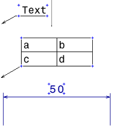
4 point on each corner of the annotation bounding box without taking into account the leader
Note: Annotations cannot be partially clipped.