From the 2D Layout for 3D Design window,
click
 and select Mechanical > Drafting.
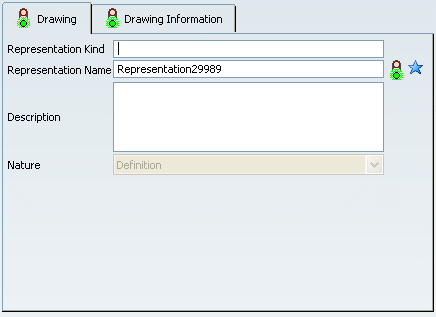
The Drawing / Representation DS dialog box is displayed,
allowing you to enter information related to your new drawing representation.

The Drawing tab lets you define general attributes
and is described in the Creating an Object user task in
the Infrastructure User's Guide.
Don't forget to fill in the Representation Name
field. By default, a name RepresentationX (where X is a number)
is specified.
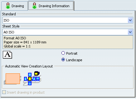
Click the Drawing Information tab.
Note:
When creating a drawing from a layout, the Insert drawing
in product option cannot be selected.

Select a standard, a sheet style and an orientation.
The sheet style defines among other things the sheet format, paper size
and scale.
Specify if you want to create an empty sheet (selected
by default) or if you want to generate all views from the 2D layout.
For the purpose of this scenario, select Generate all 2D Layout
views.
Click Finish.
When the drawing is created,
the Drafting workbench is activated.
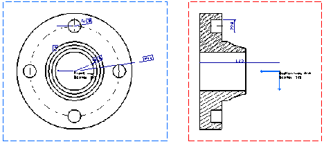
The created drawing is displayed with the same views as in the layout.
Notice that elements which are white in the layout are converted to
black in the drawing.

The created views are listed in the drawing specification
tree.
