Creating a Shape and Logical Component | |||||||
|
| ||||||
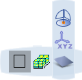
Click the arrow on the west quadrant of the Compass to open the toolbar.

Either in the toolbar, or by clicking , select the type of shape you want to create:
-
 New Component with Box
 -
 New Component with Cylinder
 -
 New Component with Sphere
 -
 New Component with 3D Shape
A balloon appears in the 3D area. The type of balloon depends upon whether you chose a basic shape (Box, Cylinder or Sphere) or a detailed shape (3D Shape):
 or
or 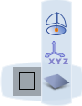
-
Optional: Basic shapes only (not 3D shapes): To define the dimensions of the basic shape, click
 and in the dialog box which appears, enter the required values and then click Close.
In the balloon, select Component
 .
.Position the shape in the 3D area using one of the following placement modes:
- To position the shape on a surface or point, click Select Surface or Point
 and then select a surface, point or edge in the 3D area.
 - To position the shape by giving coordinates, click XYZ coordinate
 . In the dialog box which appears enter your coordinates and then click OK.
 - To position the shape anywhere in the 3D area, click Selection on Compass Plane
 (Robot plane) and then select a position in the 3D area.
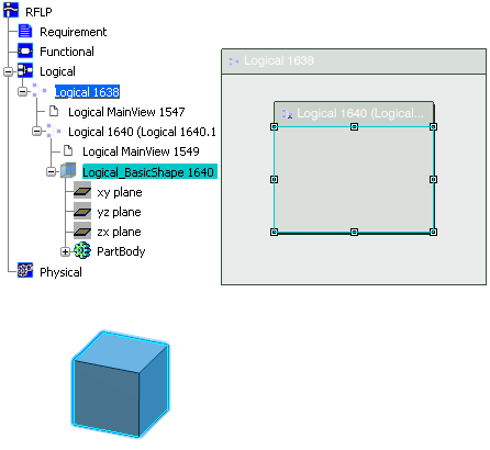
When you have clicked to position the shape:
- In the 2D view, a logical component is added.
- In the 3D view, for basic shapes, the shape appears.
- In the 3D view, for 3D shapes, the shape axes appear.
- In the specification tree, the logical component and associated logical shape (basic or detailed) are added.
In this example, a basic box is created.
- To position the shape on a surface or point, click Select Surface or Point
Notes:
- To edit the shape, double-click the shape or its reference in the specification tree.
- To move the shape, use the Robot. See Infrastructure User's Guide: Using the Robot.
- When a logical model contains a 3D Shape, you can manage the layout views to display 2D and/or 3D representations. For more information, please refer to VPM Functional Logical Editor User's Guide: Interface Description: VPM Functional and Logical Editor Toolbars: RFLP View Commands Toolbar