About Shape Placement Modes | ||||
|
| |||
The Placement Modes balloon lets you select the placement mode:
| Choose this mode... | To place a component... |
|---|---|
 |
On a surface or point |
 |
On the Robot plane |
 |
By giving XYZ coordinates |
Surface or Point
This section describes how to use the Surface or Point shape placement mode to position shapes.
Surface or Point is the default shape placement mode.
As you move the cursor in the 3D area, the square and cross indicates the plane and current position on the plane.
Click to select a location.
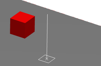
Note: No constraints are defined between the selected point and the component.
![]()
Robot Plane
This section describes how to use the Robot Plane shape placement mode to position shapes.
To define the plane on which you want to place shapes, drag the Robot and drop it onto a location, for example the face of an existing shape. The privileged Robot plane aligns itself with the selected plane.
As you move the cursor in the 3D area, the coordinates and cross lines indicate the current robot plane and coordinates.
Click to select a location.
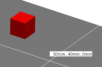
Note: You can use snap capabilities when placing shapes on the XY plane.
![]()
XYZ Coordinates
This section describes the options in the Define coordinates dialog box which you can use to position a 3D shape.
Choose one of the following reference points as the origin of the XYZ coordinates:
- To use the origin of a shape, select the shape.
- To use the default origin, click
 .
. - To use the robot location, click Robot location.
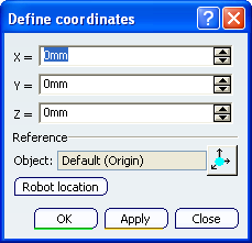
Tip: You can adjust this reference point at any time during positioning of a shape. Enter values for X, Y and Z or use the arrows to change the values.
In the example shown, X and Y are both set to 50mm. The green arrows show these as vectors from the origin.
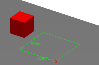
To position the shape, do one of the following:
- To position the shape and immediately close the dialog box, click OK.
- To see the shape at the coordinates in the dialog box, click Apply. If you want to adjust the position of the shape, change the values of X, Y and Z and then click Apply again. When you are happy with the position of the shape, click Close; the dialog box closes.