Allocating a Logical Component to the End of a Pathway | |||||||
|
| ||||||
Select a Pathway Segment. The Edit Pathway and 3D Allocation commands appear in a balloon:
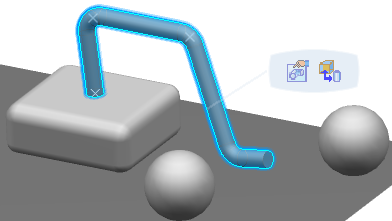
In the 3D view, select a pathway segment. The 3D Allocation dialog box is displayed.
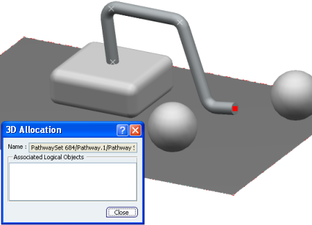
A red marker appears at one end of the pathway segment to indicate the point to which the Logical Component will be allocated. The name of the pathway segment appears in the 3D Allocation dialog box.In the 2D view, select one or more Logical Components.
You can only select a component that is not already allocated to the pathway segment.
If a 3D shape is associated to the Logical Component, a dotted line appears between the shape and the end of the pathway segment. If a 3D shape is not associated to the Logical Component, a blue dotted line appears at the end of the pathway segment.
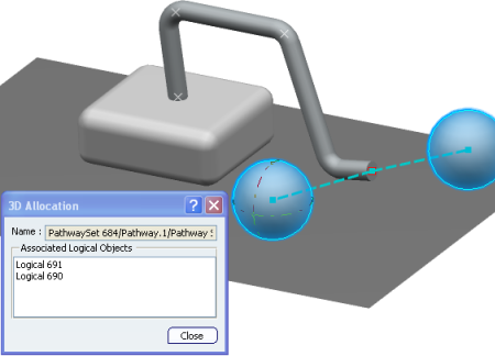
Select one of the allocated Logical Components to see the highlight between this component and the end of a pathway segment.
You can see that the Logical Component is highlighted as well as the dotted line between this component and the end of the pathway segment:
 .
.
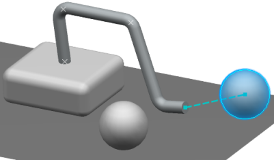
Tip:
If you select an allocated Logical Component in the RFLP tree or in the 2D view, the point to which it is allocated is highlighted by a colored dot in the 3D view.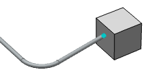 |