Allocating a Logical Component to a Space Volume

This section describes how to allocate logical components to a space volume.

A space volume represents a volume (for example, a compartment within the hull of a boat) in which components are located. The space volume is not connected to anything, it only acts as a container; the 3D shape representation of the space volume cannot be connected via pathway connection points and pathways to other components.

Note: Logical components do not necessarily have associated shapes.


Before you begin:
  1. Open the Space Allocation workbench: Click Start > Systems > 3D For Logical Systems > Space Allocation
  2. Create a space volume.
  3. Open the Logical 3D Architecture workbench: Click Start > Systems > 3D For Logical Systems > Logical 3D Architecture
Related Topics
Allocating a Logical Component to an Equipment Center
Allocating a Logical Component to the End of a Pathway
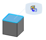
  1. In the 3D view, select the space volume.

    A balloon appears.

  2. Click Create 3D Allocation Associate Equipment Center to Logical Objects.

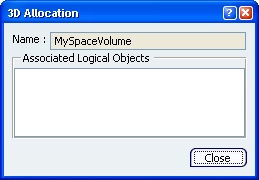
    The 3D Allocation dialog box appears.

    The name of the space volume is in the Name area of the dialog box.


  3. Optional: Click Show or Hide Command Dialog to hide the dialog box.

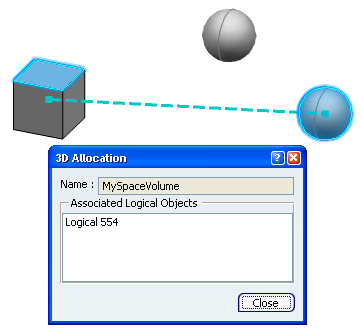
  4. In the 2D view, select the logical component you want to allocate to the space volume.

    You can only select a component that is not already allocated to the space volume.


    • The name of the logical component appears in the Associated Logical Objects area of the dialog box.
    • If a 3D shape is associated to the logical component, the shape is highlighted and a dotted line links the shape with the space volume.


  5. Optional: To remove a component from the list in the dialog box, click the name in the Associated Logical Objects area of the dialog box.

    The component is removed from the list.

  6. Optional: To allocate another logical component to the space volume, select the logical component.

    It is added to the list in the dialog box.

  7. When finished, click Close to exit the command.

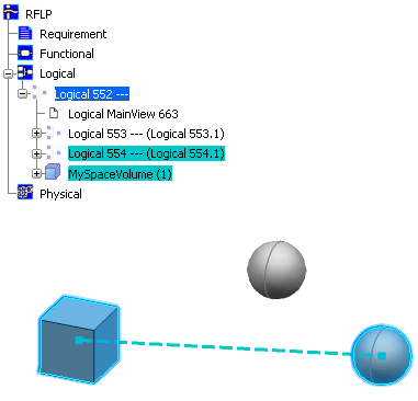
  8. In the RFLP tree or 2D view, click the component you have just associated to the space volume.


    • In the 3D view, the component is highlighted, the associated space volume is highlighted and a dotted line links the two.
    • In the RFLP tree, the associated space volume is highlighted.