Allocating a Logical Component to an Equipment Center | |||||||
|
| ||||||
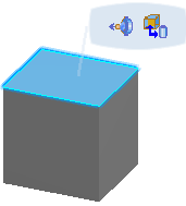
In the 3D view, select an equipment center.
A balloon appears.
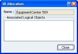
The 3D Allocation dialog box appears.
The name of the equipment center is in the Name area of the dialog box.
Optional: Click Show or Hide Command Dialog
 to hide the dialog box.
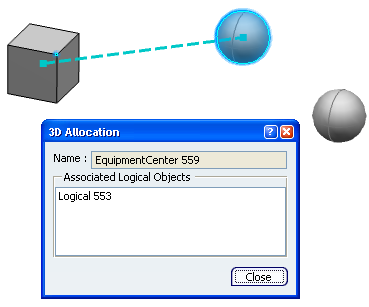
In the 2D view, select a logical component.
You can only select a component that is not already allocated to the equipment center.
- The name of the logical component appears in the Associated Logical Objects area of the dialog box.
- If a 3D shape is associated to the logical component, the shape is highlighted and a dotted line links the shape with the equipment center.
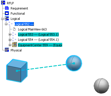
In the RFLP tree or 2D view, click the component you have just associated to the equipment center.
- In the 3D view, the component is highlighted, the associated equipment center is highlighted and a dotted line links the two.
- In the RFLP tree, the associated equipment center is highlighted.
 .
.