Defining Interference Probes | ||||||
|
| |||||
Click Interference Probe
 .
.
The Interference Specifications dialog box appears.
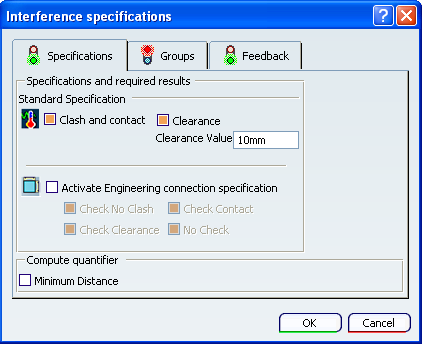
For more information, see Interference Simulation Dialog Box.Important: By default, the Clash and contact check box is selected and cannot be cleared. Customize the 3D display for each interference probe in the Feedback tab.
- Select the Display interferences list option to access the immersive interference analysis tool .
- Select the Display interferences list option to access the immersive interference analysis tool
The parts that intersect are highlighted; a red color-coded interference curve appears during the preview and is calculated during the computation of a scenario. See Simulating and Generating Results. If you selected the Clearance option, parts that are within the specified clearance distance of each other are also highlighted.
If you selected Display interferences list option and clicked , an immersive analysis interference list that provides probe information—including names, detailed specifications, issue types, intersecting products, and clearances values—is automatically displayed. The immersive analysis interference list consists of a subset of the interference analysis tools available in Interference Management product. See Product Interference Management User's Guide for more information.
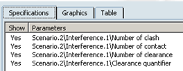
For each simulation step, the number of detected contacts, clashes, minimum clearance values, or clearances is stored in the results and can be seen in the Kinematics Postprocessing workbench using the view scenario results capability.