Load Parameters Creating and Editing | |||||
|
| ||||
Create Load Parameters
This describes how to create a load parameter.
Click Inserts a new load
 .
.Select the manikin hand.
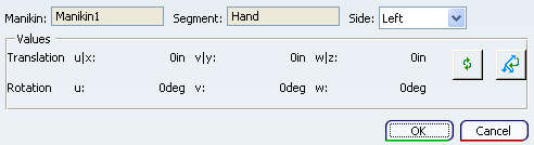
The Load Definition dialog box appears.

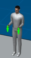
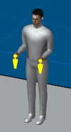
In the Magnitude section type in 5 for the left and right hand.
The load representations (forces acting on the hands) appears in the 3D view as two green arrows.
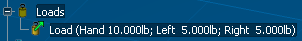
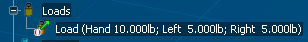
Expand the manikin specification tree.
A description (total, right, and left force magnitudes) is under the Loads node.
![]()
Editing Load Parameters
This explains how to edit the load parameters.
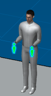
Double-click the Load by using the descriptions for picking the required load from the specification tree.
The Load Properties dialog box appears, and the arrows change color.
Note: If the total magnitude is set to 0, the load is removed from the Loads node in the specification tree.
![]()
Activating / Deactivating Load Parameters
This describes how to activate or deactivate load parameters.
Select Deactivate from the contextual menu.
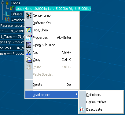
The load node is deactivated (as shown by the deactivate symbol) and the load representations in the 3D view changes color.
Note: The display options are located in the Tools > Options > Ergonomics > Human Builder > Display tab.
![]()
Load Parameters with a Define Offset
This describes how to activate or deactivate the load parameters that have an offset.
Select Define Offset from the contextual menu.
The Load Offset Definition dialog box appears.
Note: As just one load can be added to one segment at the time, just one load offset could be added to a load.
Finally, as for the segment offset current behavior, a load offset node for each load offset creation is added and visible in the tree under the Loads node. Each individual load offset node displays a description including the name of the load offset and the name of the segment to which the load offset is related.