More About Sections | ||||||
|
| |||||
What Are Sections?
This sub-topic provides background information to help you understand what sections are.
An aligned section view or aligned section cut is a view created from a cutting profile defined from non parallel planes. In order to include in a section certain angled elements, the cutting plane may be bent so as to pass through those features. The plane and feature are then imagined to be revolved into the original plane.
An offset section view or offset section cut is a view that allows sectioning through irregular objects, making it possible to show several features that do not lie in a straight line by offsetting or bending the cutting plane.
![]()
The Cut in Section Views Capability
This sub-topic provides information about the Cut in section views capability.
Note: As its name implies, this capability applies to section views only.
In an assembly, you can specify whether product should or should not be sectioned when generated into section views or breakout views. (This capability is not available for section cuts.)
The 3D part not to be cut, has to own a dedicated Boolean property (refer to PLM Customization documentation to add this property) named E_DrwUncutInSections, valuated as TRUE through Product > Edit > Properties.
You can also do this when overloading element properties in a generated view.
| Important: If you choose not to cut elements in section views (i.e. if you clear the Cut in section views option), note that this capability does not work for section or breakout views generated using the Approximate generation mode: selected elements will be cut nonetheless. Likewise, if you switch an exact view to the approximate mode, the elements for which you cleared the Cut in section views option will be cut in the view nonetheless. |
![]()
Patterns
This sub-topic provides information about the patterns which are used to represent sections.
Note: Patterns will not be applied to aligned sections which are tangent to 3D faces.
Patterns are defined in the standards. For more information, refer to Administration: Setting Standard Parameters: Pattern Definition.
You may modify the pattern (hatching, dotting, coloring or motif) by right-clicking it and selecting Properties from the contextual menu. This will display the Properties dialog box in which you may either select a new pattern or modify some graphical attributes of the existing pattern. For more information, refer to Interface Description: Dialog Boxes: Properties Dialog Box: Pattern Tab.
| Important: In the case of parts which use a material to which a specific pattern is associated, views generated using the Approximate generation mode do not inherit the material properties from the 3D, and therefore do not use the pattern associated to this material. Furthermore, as pattern properties are not persistent, the pattern may change after switching an exact view to the approximate mode and vice versa. |
![]()
Understanding Unexpected Results
This sub-topic provides information that may help you understand unexpected results:
Case of Aligned Sections
This sub-topic provides information that should be useful to understand unexpected results in the case of aligned sections views or aligned section cuts.
Contrary to other view types, in an aligned section view/cut, the 2D geometry seen in the view is not based on a single 3D plane, but on numerous 3D planes. However, as all generative views, the aligned section view represents only one projection plane. Then it selects only one of the 3D planes (the one corresponding to the first segment of its profile). As a consequence, some results can be different from the your expectations:
-
Symbolic representation of threads can be ill-formed.
-
When creating an auxiliary, section, breakout or box clipping view from the aligned section view/cut, the result might not be the expected one.
In these particular cases, create a view of each part to get the results you expect.
Case of Offset Sections
This sub-topic provides information that should be useful to understand unexpected results in the case of offset sections views or offset section cuts.
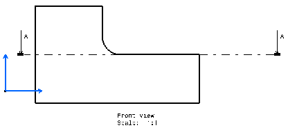
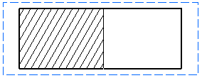
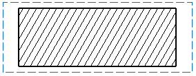
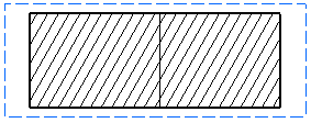
When a planar face belongs to the section profile, you may get unexpected results. For example, the section edge may or may not be displayed, and the section may or may not be represented by a pattern. Indeed, as the cutting profile can be considered as being either inside or outside the part, the result largely depends on computing tolerances. Consequently, when defining the section profile, we advise that you avoid getting into such a geometrical configuration.
The example here shows what kind of results you may get for a given
section:

Expected result:
Unexpected results:
