Creating Constructed Geometry | ||||||
|
| |||||
Click Constructed Geometry Creation

Select the surface as shown.
The Constructed Geometry Creation dialog box appears.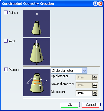
Tip: Double-clicking any automatic constructed geometry displays this dialog box. Select Axis and Plane as geometries to be generated and click OK in the dialog box.
The axis and the plane are created in the geometry.

In the specification tree, Cone Axis.1 and Gage Plane.2 representing the created axis and plane geometries are added to the Construction geometries section.
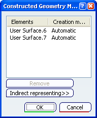
Click Constructed Geometry Management

Select the surface as shown.
The Constructed Geometry Management dialog box appears and displays the two created geometries and their creation mode, where User Surface.8 and User Surface.9 are representing geometry elements of the axis and the plane respectively.