Managing Constructed Geometry | ||||||
|
| |||||
Select the datum.
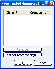
The Constructed Geometry Management dialog box appears.
Select the reference plane as shown to define the gage plane of the related surface of the annotation.
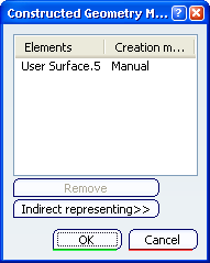
The Constructed Geometry Management dialog box is updated, the constructed geometry is created in manual mode: the associativity is managed by the user.
Click Constructed Geometry Management

Re-select the previous datum.
Click Indirect representing in the dialog box.
The Constructed Geometry Management dialog box displays the indirect representing of the previously created constructed geometry (Plane.1 is a representing geometry element, named User Surface.6, of the selected reference plane in step 3).
