Creating Thread Representation

You can create a thread representation.

The thread representation is made of three constructed geometries:


  • The plane representing the upper limit of the thread.
  • The plane representing the lower limit of the thread.
  • The cylinder representing the thread.

Note:

The thread representation display is standard dependant and will be automatically updated when you upgrade or modify the annotation set standard.

Important: You can create thread representation:

  • By selecting a Part Design thread feature
  • By selecting a thread as Part Design technological result
  • By selecting the All threads option, in this case for each Part Design thread in the 3D shape a thread representation is created.

You can also created a thread representation using Constructed Geometry Creation.

See also Constructed Geometry settings.


Before you begin: Open an existing 3D shape containing at least one Part Design thread and/or thread as technological result.
Related Topics
About Constructed Geometry
Creating Constructed Geometry
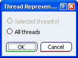
  1. Click Thread Representation Creation

    The Thread Representation Creation dialog box appears.


  2. Select Thread.1 in the Specification Tree. You can also select the threaded face in the geometry window.

    The Thread Representation Creation dialog box is updated to indicate that the thread representation will be created for the selected thread.


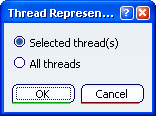
    Important: Using All threads geometry selection is useless.

  3. Click OK to validate and exit the dialog box.

    The geometrical representation of the thread is displayed in the geometry, and an item is created in the specification tree.