Click Pattern
 .
.
The Pattern dialog box appears. Default options let
you define a rectangular pattern.
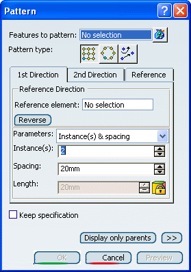
Select Protected Prism.5 as the feature to
pattern.
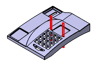
Select the xy plane to specify the first
direction of creation.
To define a direction, you can select a line or a planar
face.
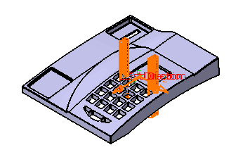
An arrow indicating the direction is displayed on the solid functional
set.
Select the Reverse button or click the arrow
to reverse the direction.
The new direction is as follows:
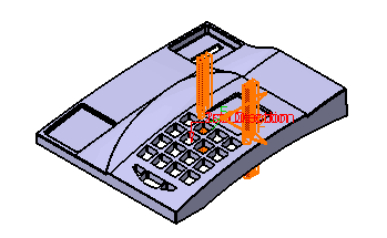
Define the parameters you want to specify. The parameters
you can choose are:
- Instances & length
- Instances & spacing
- Spacing & length
Enter 5 as the number of instances you want to obtain
in the first direction.
Define the spacing along the selected direction: enter
9.5 mm.
The pattern looks like this:
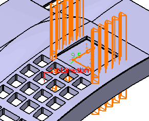
Click OK to confirm the operation.
The rectangular pattern composed of 10 instances is
created:
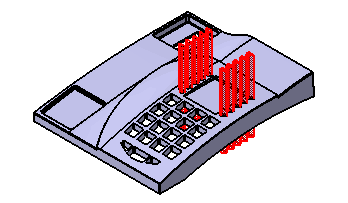
Rectangular Pattern.X is added
to the specification tree in the Solid Functional Set .X
node.