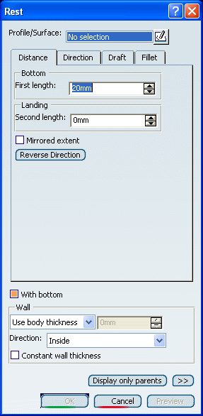
Creating a Rest | ||||||
|
| |||||
Click Rest
 in
the Functional Features toolbar.
in
the Functional Features toolbar. The Rest dialog box appears.
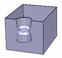
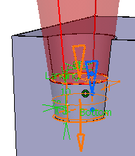
Select a closed profile.
A rest requires a closed profile on the body indicating where the rest is to be created.
Tip: If no profile is defined, clicking Sketcher  enables you to sketch the profile you need.
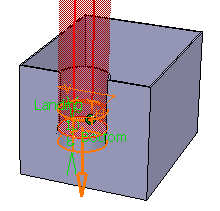
To define the landing, enter 10mm in the Second length box to define the distance from the sketch plane up to the landing. Previewing the feature lets you get an idea of what the rest looks like. As a protected area, it is displayed in red:
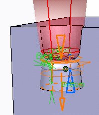
Enter the desired value in the Angle box.
The default neutral element (defines a neutral curve on which the drafted face will lie) is the Profile plane. The other possible neutral elements can be:
- Bottom
- Landing
- Plane/Surface
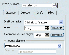
A Clearance volume angle box and associated Reverse button allows the clearance draft to be independent of the platform draft. This allows, for example, the platform draft to be used for aesthetic reasons (large draft value) and the clearance draft to be used for manufacturability (small draft value).
Click Reverse button at Angle.
Select the Landing radius check box to fillet landing edges and enter 6mm as the radius value.
If the rest is to be shelled, you can select Constant wall thickness check box. This propagates the fillets into the shell, thus maintaining a constant wall thickness.
Click OK to confirm and create the rest.
The rest is created. The protected area is hidden. Rest.X is added to the specification tree in the Solid Functional Set.X node.