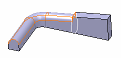
Creating a Tri-tangent Fillet

You can create a tritangent fillet that involves the removal of one of the three faces that has been selected.


Before you begin: To create a Tritangent Fillet, you need a model that has three faces and two of which are supporting faces.
Related Topics
Creating a Rectangular Pattern
Creating a User Pattern
Using the Display Only Parents Option to Retrieve a Creation Context
  1. Click Tritangent Fillet .

    The Tritangent Fillet Definition dialog box appears.

  2. Select the two faces of each side as the faces you want to fillet.
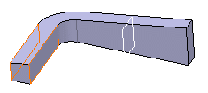


  3. Select the top face as the face to remove.
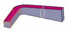


  4. Optionally, click Preview to see the fillet to be created.
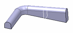


  5. Click More >> to access the Limiting element option.

  6. Select the plane as the limiting element.

    Important: Contextual commands creating the limiting elements you need are available from the Limiting element box:
    • Create Plane: see Generative Shape Design User's Guide: Creating Wireframe Geometry: Creating Planes.
    • XY Plane: the XY plane of the current coordinate system origin (0,0,0) becomes the limiting element.
    • YZ Plane: the YZ plane of the current coordinate system origin (0,0,0) becomes the limiting element.
    • ZX Plane: the ZX plane of the current coordinate system origin (0,0,0) becomes the limiting element.
    • Create Join: joins surfaces or curves. See Generative Shape Design User's Guide: Performing Operations on Shape Geometry: Joining Surfaces or Curves.
    • Create Extrapol: extrapolates surface boundaries or curves. See Generative Shape Design User's Guide: Performing Operations on Shape Geometry: Extrapolating Surfaces and Extrapolating Curves.

    If you create any of these elements, the application then displays the corresponding icon in front of the Limiting element box. Clicking this icon enables you to edit the element.

    An arrow appears on the plane to indicate the portion of material that will be kept.

    Important: Clicking on the arrow reverses the direction and therefore indicates the opposite portion of material that will be kept.

  7. Click OK.

    The faces are filleted. The fillet is trimmed to the plane. The creation of this fillet is indicated in the specification tree.