Click Fitting
 in
the Basic Features toolbar (Body Modifiers sub-toolbar)..
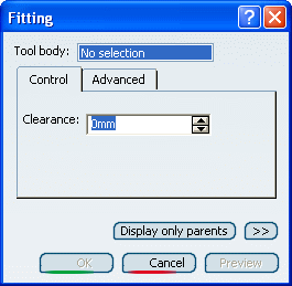
The Fitting dialog box appears.
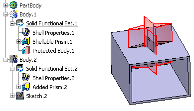
Select Solid Functional Set.2 as the
solid functional set that will perform the operation into Solid
Functional Set.1.
In the Clearance box, enter a value to define
a clearance.
The clearance defines a space around the tool body, based on a specified
value, that extends the protected volume of the fitting by that value.
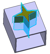
Click Preview to see the result:
If you want to define specific clearances between one
or more faces and Solid Functional Set.1, click the
Advanced tab.
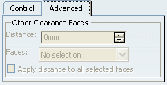
Select the face of interest, then, for instance, enter
4 as the distance value.
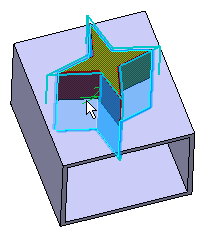
Click Preview to see the result:
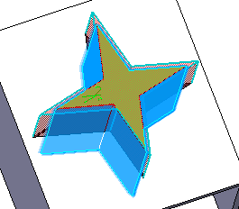
Click OK to confirm and create the fitting.
Fitting.X is added to the specification tree
in the Solid Functional Set.X node.
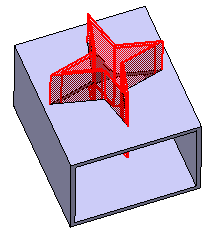
The volume that is removed during the fitting operation is
made a protected volume. No other entity in the same solid functional
set can penetrate into the protected volume. However, entities
from other solid functional sets can penetrate it.
A fitting feature does not create walls in the shelled volume
of the target solid functional set. If you want the fitting
feature to inherit the shell thickness of the target solid functional
set, thus creating walls of the same thickness, use the
Push or
Pull command.