Pushing a Body to Deform a Shell | ||||||
|
| |||||
Push a Body
You can push a selected body into another body and carry out various operations (filleting and removing the unnecessary faces) on it.
Click Push
 in the Basic Features toolbar (Body Modifiers
sub-toolbar).
in the Basic Features toolbar (Body Modifiers
sub-toolbar).The Push dialog box appears.
Enter a value in the Distance box.
You can click Preview to see the result.
The clearance is the protected volume around Body.2 that separates it from Solid Functional Set.1.
Set Enter thickness in the Wall area and enter 6mm for instance in the value box.
Important: The walls produced by the Push feature are defined by one of the two options available from the Type drop down list: - Use body thickness: the push wall thickness is that of the active shelled body thickness.
- Enter thickness: Enter the value you want. After this option is selected, the value box becomes available. Wall thickness values can only by positive values.
Choose between Intersection with Core/Cavity, Intersection with Core or Intersection with Cavity from the dropdown list to add an intersection fillet.
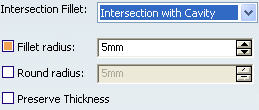
If you want to add material to the feature, select the Fillet radius checkbox, if you want to remove material from the feature, select the Round radius checkbox.Select the Preserve Thickness checkbox if you want to keep the thickness applied on the feature.
Click OK to confirm and create the push.
Push.X is added to the specification tree in the Solid Functional Set.X node.
Select the face as below to remove. The selected face will be removed.

Tip: In case you want to remove: - A face from the selection: Select the face from the geometry.
- All selected faces: Use the Clear Selections contextual command available from the Faces box.
Important: By selecting faces in Faces to remove in Openings, the walls facing to the selected face will be removed. This feature is useful for the vent shapes. The clearance option on selected faces will be compatible with the selection of faces to remove. Click OK to confirm and create the push.

![]()
Define Additional Clearances
You can apply clearance value between the pushing body and the existing body.
The clearance is the protected volume around Body.2 that separates it from Solid Functional Set.1 (see scenario above).
If you want to define other clearances between specific faces and Solid Functional Set.1:
Enter a distance value.
You can then click Preview to see the result:
If you want to apply the same clearance to other faces, select the faces and select Apply distance to all selected faces check box.