Measuring Distances Between Geometric Entities | |||||||
|
| ||||||
Measure Between Two Geometric Entities
You can measure the distances between the two geometric entities.
Select Measure Between
 in the Review Creation toolbar.
Several things now happen:
- The arrow pointer
 changes to the measure pointer
  . Depending on the position of the measure pointer, it may also show a symbol indicating the object you can select with it. For a list of all the measure pointers, see Pointer Transformation.
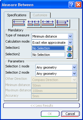
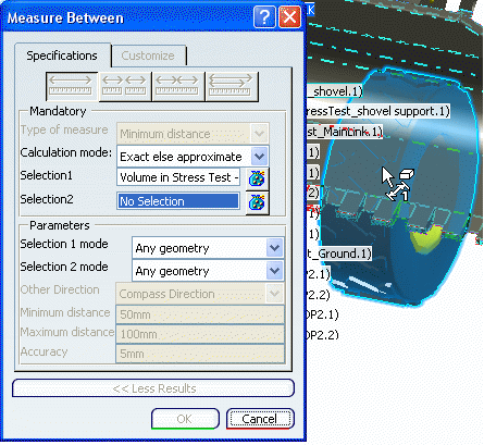
 - The Measure Between dialog box appears with the Specifications tab activated:
- The arrow pointer
Move the measure pointer
over the geometry.
You will see that as you do this the symbol at the top right of the pointer changes to reflect the geometry type and to help you with your selection:
As you move the pointer, dynamic highlighting of geometric entities helps you locate the item to be selected.
Click when the pointer is above the object to be selected first in the Measure Between operation.
Several things now happen:
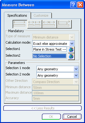
- the selected object is highlighted in the geometry and in the specification tree.
- In the Measure Between dialog box, the Type of measure field is grayed out and both the geometry type and name of the object you selected are indicated in the Selection1 field:
- A MeasureBetween item is created in the specification tree under the Notes branch with the name MeasureBetween.x where x is its number:
Important: The symbol
appears when a Measure Between is created in design mode.The symbol
 appears when the measure is not associated with the selection you made and will therefore not be affected by any modifications you make to the selection.
The symbol
 appears with an associative measure, if the linked geometry is not in design mode.
 - To rename the measure, right-click it and change the name in the Properties dialog box.
- The pointer changes to
 .
.
Now make the second selection.
The Customize tab and More Results >> section in the Measure Between dialog box are activated.
For information about the Customize tab and More Results >> section, see Customizing Measurements.
An information box appears giving you various items of information about the Measure Between operation and the two selected entities. To move this box, click and drag it. A full list of detectable objects is provided in Pointer Transformation. Here is an example:
If a measure using the mode Maximum Distance, Maximum Distance from 1 to 2 or Measure along a direction fails, an error message appears.
For more information on these modes, see Refining Criteria.
To edit an existing measure, you have three options:
- double-click the measure in the specification tree.
- double-click the appropriate information box in the geometry.
- right-click the measure in the specification tree and, in the contextual menu that appears, select [measure_name] object>Definition....
Once created in the specification tree, the selections of non-associative measures cannot be modified. If you click the
 button, a warning message appears:
If you click Yes, the lists for both the first and second selection will be cleared. You can now make new selections.
If you click No, the selection list remains unchanged.
Note that you can reopen any Measure to access the Customize tab and Results section.
Important:
|
![]()
Multiselect Geometric Entities
You can make multiselections by putting several entities into a selection list. In the Measure Between operation, such a selection list can be used for the first or second selection. In this way, the distance between two groups of entities can be measured.
To add other entities to the first selection, click the
button to the right of the Selection1 field in the Measure Between dialog box.
The Measure Selections dialog box appears:
You may find it useful to use the Complementary Selection button for quick Product selection (see Making a Complementary Selection).
Select the other entities you want to be part of the first selection:
Every selection you make is interactively displayed in the Measure Selections dialog box:
When you have finished adding entities to the first selection, click the Selection2 field (or press the Ctrl key) to add entities to the second selection.
Use the
button if you need to view the selection list.You can go back and forth between the Selection1 and Selection2 fields using the Ctrl key.
Note that whereas for a single selection the information box is directly attached by an arrow to the selected entity, for a multiselection it is attached to the intersection of the dashed lines coming from the center of each selected entity:
![]()
Make a Complementary Selection
The Complementary Selection option can be useful for quick product selection. Once you have made your first selection, complementary selection enables you to retrieve, in the second selection list, all the other products in the session.
Make your first product selection (in the geometry as shown below or in the specification tree):
Use the
button to open the second selection list and press the Complementary Selection button.
All the other products in the session are selected and placed in the second selection list:

Example of product selection
Let us assume the products look like this:
If you select Product 1 for the first selection, the complementary selection will be Product 8.
If you select Product 4 for the first selection, the complementary selection will be Product 5, Product 6, Product 2 and Product 8.
Important: - All selections, in both selection lists, must be Products.
- The first selection list must not be empty.
- The second selection list where the want to place the complementary Products must be empty.

![]()
Measure in the Specification Tree
You can also make a measurement between two geometric entities (or groups of entities using multiselection) in the specification tree.
- In the specification tree, select the two geometric entities (or groups of entities using multiselection) that you want to measure.