In the Meshes toolbar, click Beam Mesh
 . .
The Beam Mesh dialog box
appears.
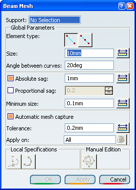
Select a 1D geometry as Support.
The local specifications are now available. Select the Element type you want to create
(linear or parabolic). - If you want to mesh the support using 1D elements without
intermediate node, select Linear.
- If you want to mesh the support using 1D elements with
intermediate node, select Parabolic.
In the Size box, enter a value to specify the
global size of 1D mesh element. To ignore existing vertices of the initial topology,
enter a value in the Angle between curves box. Optional: Add sag
specifications to refine the mesh in curve-type geometry. The sag is the
distance between the mesh elements and the geometry. - If you want to specify an absolute sag, select the
Absolute sag check box, and enter a value in the
Minimum size box.
- If you want to specify a proportional sag, select the
Proportional sag check box, and enter a value in the
Minimum size box.
Optional: If you want to
create a 1D mesh compatible with an existing mesh, select the
Automatic mesh capture check box.
- Enter a tolerance value in the Tolerance box.
- Select the mesh you want to capture.
Optional: To project external points on the geometry: - Click Point Projection
 . . The Point Projection dialog box appears.
- Select the points you want to project.
- In the Tolerance box, enter a tolerance value.
- If you want to project the selected points on the geometry, select the Projection on geometry check box.
- Click OK.
Optional: To distribute nodes: - Click Edge Distribution
 . . The Edge Distribution dialog box appears.
- Select the supports. Multi-selection of supports is
available.
- Select one of the
following distribution types in the Type list:
- Uniform to distribute all nodes with the same
distance.
- Arithmetic
- Geometric
- User law
- Define the distribution parameters.
Here are examples of the distribution result depending on
the selected distribution type:
- If you selected Uniform and the number of
edges is equal to 10, the distribution looks
like:

- If you selected Arithmetic or Geometric
without symmetry, the distribution looks like:

- If you selected Arithmetic or Geometric
with symmetry, the distribution looks like:

- Click OK.
Click Apply. Optional: Edit manually the mesh. You can manually move, freeze and unfreeze nodes or split and condense
edges of 1D beam elements. Click OK.
You have now to apply a 1D property. See Creating 1D Properties.
|