Create a New Finite Element Model Representation
You can create a new finite element model representation and access the Finite Element Modeling workbench.
From the bar, click
 ,
and select . ,
and select . Each
time you enter the Finite Element Modeling workbench using this icon, a new finite element model
representation is created.
Depending on whether a product is open and displayed or not, the use of the
 icon gives different results:
- If no product is open or active, the Product dialog box appears.
- If a product is open and displayed, the Finite Element Modeling dialog box appears.
If no product is open, enter the name of the product and the finite element representation in the product dialog box. - In the Product tab, modify the name of the product.
- In the Finite element model tab, modify the name of the finite element model
representation.
- Click Finish.
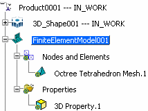
A product containing an empty finite element model
representation is created:

If a product is open and contains subproducts with finite element model representations, you have to choose the type of finite element model representations you want to create: simple or assembled. - To create an assembly of finite element model representations, select Create an assembled representation.
- To create a simple finite element model representation, select Create a stand alone representation.
To create a default mesh and a default
property in the finite element model representation, select the Initialize content check box.
- If the product contains only one 3D shape, the finite element model representation is automatically linked to the 3D shape, and a
default Octree tetrahedron mesh and a default 3D
property are automatically created.

- If the product is an assembly product that
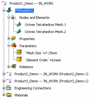
contains several 3D shapes and if you have selected Create a stand alone representation, several Octree
tetrahedron meshes and 3D properties are created
(one per PartBody). All the meshes are created with
the same mesh size (ratio of the global bounding
sphere), the same sag (ratio of the mesh size), and
the same element type (linear) using knowledge
parameters and relations.

To create an empty finite element model representation, clear
the Initialize content check box.
Click OK in the Finite Element Modeling dialog box. The Finite element model / Representation dialog
box appears. Note:
The dialog box contains only the Finite element model tab because the
product is already created.
Optional: Modify the
name of the finite element model representation in the Name
box. Click Finish. The finite element model representation is created, activated
(highlighted in blue in the specification tree), and opened in the Finite Element Modeling workbench.

Edit an Existing Finite Element Model Representation
In a product containing 3D shapes and finite element model
representations, you have to activate one particular finite element
model representation to work in this representation and to access the commands of the Finite Element Modeling workbench.
- To activate a finite element model representation, double-click an element of the finite element model representation
in the specification tree.
|
![]()


