Create Harness / Connector Links
You can create links between a Harness and Connectors allowing you to manipulate the Harness composition more easily.
From the RFLP structure tree or from the 2D representation, select
the logical component to be linked, Logical Harness 1.
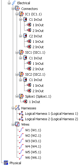
Select Harness / Content Links  from the Electrical toolbar. from the Electrical toolbar.
From the RFLP structure tree or from the 2D representation,
select SIC1 and you obtain:
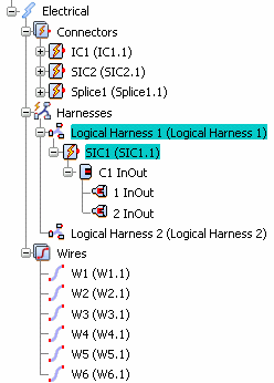
An electrical link is created only between
Logical Harness 1 and SIC1. Under the Harnesses node, Logical Harness 1 contains SIC1.
To remove the link, click SIC1.
Deactivate Harness / Content Links. You will now link the Harness to the SIC and the Splice.
Re-activate Harness / Content Links. From the RFLP structure tree, select
Logical Harness 1 and SIC1 and Splice1.
In the Specification Tree, note that Logical Harness 1 contains SIC1, Splice1 and the two wires.
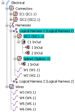
An electrical link is created between the harness and the SIC and Splice. An implicit link exists between the Logical Harness 1 and the wires as the wires' ends are connected to the Pins under this Harness. The new definition of the Harness content facilitates the manipulation of the Harness composition. Both version and definition are suppported.
Deactivate Harness / Content Links.

Create Harness / Connector Port Links
You can create Harness / Connector Port Links.
From the RFLP structure tree or from the 2D representation, select
the logical component to be linked, Logical Harness 1.
Select Harness / Content Links  from the Electrical toolbar. from the Electrical toolbar.
Select the Connector Port (C1) of the Interface Connector.
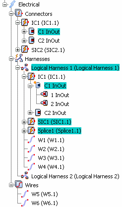
In the Specification Tree, note that the symbol of C1 has changed: an orange mask appears on it, illustrating the electrical link between the harness and C1. Moreover, an implicit link is created between the harness and the wires W3 and W4. Deactivate Harness / Content Links. Re-activate Harness / Content Links. From the RFLP structure tree or from the 2D representation, select Logical Harness 2 and C2 (of IC1) and SIC2.
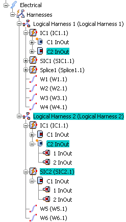
An electrical link is created between Logical Harness 1 / C2 and between Logical Harness 1 and SIC2. And an implicit link exists between Logical Harness 2 and W5 and 6. Note that the Connector node has disappeared because all its Connectors Ports are now linked to a harness.
Deactivate Harness / Content Links.
It is recommended to use implicit links, rather than a Model link, between the Harness and Wires or Cables.
|
![]()


