Define an Electrical Connector Component
You can create a logical component and extend it into
a Connector component.
This task shows how to extend an existing logical component into an electrical component.
Select Electrical Component Extension  from the Electrical toolbar. from the Electrical toolbar.
From the RFLP structure tree or from the 2D representation, select Jack Connector.
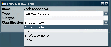
The Electrical Extension dialog box appears.

From the Type drop-down list, select a type:
- Connector component: to create a connector (splice, connector shell, single insert connector...).
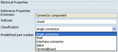
If needed, enter a description in the Subtype field. From the Classification drop-down list, select a Classification: Single connector, Shell, Interface connector, Splice or Terminal Board. You can define the Classification of a connector during its extension, you can also edit its Properties to change Classification. Click OK to close the dialog box and add an electrical extension to the logical component. A Connector Component node (Jack Connector) is created. Under the Extensions node, note that a connector node is created to store all the connectors. In our example, it aggregates a connector component node containing our extended electrical component (Jack Connector). Right-click the electrical component, then select Properties from the contextual menu. The Properties dialog box appears. The Electrical tab has been created to display the electrical properties.

Note:
You can use the Spreadsheet editor to create a reference and extend it to a logical connector component , then instantiate it under the root reference.

Defining an Electrical Busbar Component
You can create a logical component and extend it into
a Busbar.
Select Electrical Component Extension  from the Electrical toolbar. from the Electrical toolbar.
From the RFLP structure tree or from the 2D representation, select Busbar 400A.
The Electrical Extension dialog box appears.

From the Type drop-down list, select a type:
- Busbar: to create a busbar.
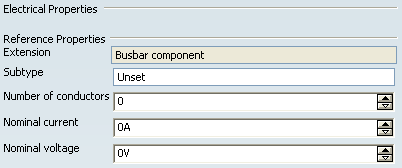
If needed, enter a description in the Subtype field. Click OK to close the dialog box and add an electrical extension to the logical component. A Busbar Component node (Busbar 400A) is created. Under the Extensions node, note that a Busbar node is created to store all the Busbars. In our example, it aggregates a Busbar component node containing our extended electrical component (Busbar 400A). Right-click the electrical component, then select Properties from the contextual menu. The Properties dialog box appears. The Electrical tab has been created to display the electrical properties.

Note:
You can use the Spreadsheet editor to create a reference and extend it to a logical busbar , then instantiate it under the root reference.
|