Rotating Segments | ||||||
|
| |||||
Click Live Manipulator
 in the Manipulator toolbar.
The Rotate command allows to move a sub-part of electrical geometry. It is a rotation transformation from a pivot that is a branch end or point.
Select a branch or segment you want to rotate in the geometry space:
-
the branch becomes highlighted
-
Live Manipulator toolbar appears near the branch, to show the current option of the manipulator
-
the Robot automatically snaps onto the other end of the branch, it is the center of rotation. The Robot is also called Virtual Roll Center. It is visualized like a disk and an arrow.

For more information about selection modes (Punctual, Local and Global), please refer to Accessing Commands in Live Manipulator.
Multi-selection of the branch from the same junction is possible with the Ctrl key.
Selection in the Specification Tree is not possible because the end of branch is mandatory since the exact position of the selected point has to be known. The branch point or branch end furthest to the point of selection is selected as the rotate point and the Robot moves on it.
In a sub-geometry, several branches may be impacted by rotate and they are highlighted.
The rotation will be done in a plane parallel to the active plane. The default General Parameters is the one you have defined in the Harness Flattening Parameters dialog box at the beginning of your session.
There are two ways of selecting the rotation pivot:
-
If the Branch Point of a Branch is selected as the Rotate pivot point, then the Branch will be split at this point and the split Segments will be put in a new Branch.
-
If the Branch End is selected as the Rotate pivot point, then no split will be done and the whole Branch will be rotated.
If you want to see a message when during the branch split when rotating segments, you can check an option in Tools > Options > Equipment > Electrical Discipline > Electrical Harness Flattening. For more information, please refer to General.
-
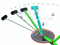
Select the branch and move it in real time where you want the sub-geometry to do the rotation. Thus you can see the clashes.
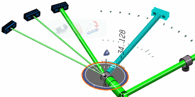
A graduation circle and a number show the value of rotation angle.

You can specify the rotation by:
- Specifying the main direction: translation and radius are defined with the Virtual Roll Center.
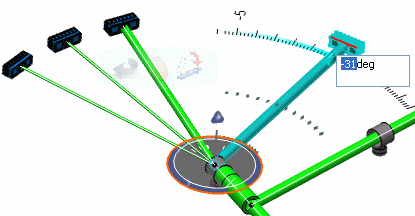
- Entering an angle value: graduation helps you to display the value of rotation or translation parameters.
Select the blue arrow at the far end of the branch. Then, an editable field or spinner dialog box pops up. You can set the value.

A message is displayed when the angle is inferior to the one defined by default or by the Business Rule.
If you want to cancel the command, you can press Escape on keyboard: the electrical geometry position is restored. Or you can select another command and the Rotate operation aborts.
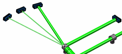
If you want to validate the preview, click in the 3D background. In this case, the rotation is really executed, with a modification of the geometry data.
This may take some time depending on the amount of data to handle.

Important: - Rotate with Split is allowed only when you press Ctrl while selecting the branch. Otherwise normal whole branch Rotate will happen.
- The Split Pivot flag will be visible for Rotate allowed on branch points. This Split is specific to Electrical Harness Flattening and after the Rotate Split, there is no change in the Specification Tree of 3D harness data:
- When rotating segments in a closed harness loop, the loop is automatically opened at the free end of the selected segment and a green line created to serve as a reminder that a link exists.
- Length tolerance cannot be applied on a Roll section & vice-versa.
- Multi-profile segments: in order to avoid twisted and impossible configurations, the local V-axis of the profile sketch is kept aligned with the normal direction of the active plane.
- Mechanical parts: a dashed green line visualizes the link between the segment and mechanical part. Use the compass to reposition the part properly.