General | ||
| ||
Synchronization Report Repository

- Path
- Indicate the folder path where you want to save the synchronization
report html files.
 By default,
This field contains: ...\DassaultSystemes\CATTemp.
![]()
Configuration Management

- Extract the variability space
- When this option is activated, the variability space is extracted
from the 3D Design into the 3D Flatten and it is synchronized only
once as it is not possible to change the value of the variability
space after affectation.
During the synchronization command, the variability space of the father element is checked and automatically synchronized along with the effectivity of the child element. The effectivity of instance is synchronized only if the parent product has a variability space:
- The effectivity of 3D Design is read and compared to the effectivity of 3D Flatten, if it is included inside, the flatten effectivity is maintained.
- The effectivity of 3D Design is read and compared to the effectivity of 3D Flatten, if it is NOT included, the flatten effectivity will be replaced by the same effectivity of 3D Design.
For more information about variability space and effectivity in 3D Flatten, please refer to Synchronizing the Configuration on Electrical Component in the Electrical Harness Flattening User Guide.
When this option is NOT activated, the variability space is not extracted, the father element has no variability space and the effectivity is not synchronized during this Extract. A message appears in the Synchronization Report. See About the HTML Report in the Electrical Harness Flattening User GuideIt allows you to define your own variability space in 3D Flatten. You can either copy effectivities from 3D Design or add Manufacturing effectivities on product for example. Finally you can synchronize.
 By default,
this check box is selected.
![]()
Warning message on branch split in Rotate and Arrange Junction command

- Warning message on branch split in Rotate and Arrange Junction command will be
- If you want to see a warning during the branch split when rotating segments or arranging junction in branches, select the Shown option. For more information about these commands and branch split, please
refer to Electrical Harness Flattening User's Guide: Using the
Live Manipulator: Rotating Segments and Arranging
Junctions.
 By default,
the Shown check box is selected.
![]()
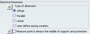
Electrical Dimension

- Type of Dimension
- When you select the Measure Points in the 3D space, the Electrical Dimensions dialog box appears allowing you to select the type of curvilinear dimension:
- Offset: displays the dimension line as an offset segment of the projection of the measured segment.
- Parallel: displays the dimension line as a parallel segment of the projection of the measured segment.
- Linear: displays the dimension line as a straight line, parallel to the direction defined by the limit points of the measured segment.
- User define during creation: if you select this setting, the previous options appear in a window entitled Multiple Dimensions or Overall Dimension when you have clicked these commands. You can choose / change the types of curvilinear dimensions when creating them.
- Measure Point is always the middle of support and protection
- If you select this option, the middle of the support or protection will be considered as the only Measure Point on the support or protection.
For more information, please refer to Electrical Harness Flattening User's Guide: Creating and Removing Electrical Dimensions.
