Synchronize 3D Flattened Geometry
You can define what you want to synchronize.
In the initial design data, select a segment and modify its length, diameter, bend radius, instance name or color. Save your data. Switch back to the extracted data.
Click Synchronize  . .
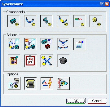
The Synchronize dialog box is displayed:

It lets you define what you want to synchronize:
- Components allows you to select which components you want to update: You can select as many components as needed at the same time. For details, see About Synchronization.
- Actions allows you to customize the actions during the synchronization step: You can select as many actions as needed. For details, see About Synchronization.
- Options lets you select the operations to run during synchronization. For details, see About Synchronization.
During the synchronization step, the selected options only will be performed. An HTML report will be generated accordingly and will only show the selected options. Click OK to validate. A status bar appears showing the synchronization progress. Here are the different steps that can be seen through the synchronization process according to the options previously selected:
- Analyze step is processing (here the electrical connections are also automatically selected)
- Replaced components synchronization is processing
- Removed components synchronization is processing
- Segment structure synchronization is processing
- Added components synchronization is processing
- Attributes synchronization is processing
- Knowledge parameter synchronization is processing
- Generating Html report
An HTML file is generated in the synchronization report repository if Html Report is selected. For more information about the html report, see About the HTML Report. The extracted document is updated if Simulation is not selected:
- The Synchronize property of components that have been modified is set to True.
- Resetting the synchronization history of components switches the Synchronize property back to False.
Thus you can visualize what electrical components have been modified in the initial model. Note: If both Design Length and Flat Length have been increased (see Applying Length Tolerance), this Length Tolerance value is maintained on the segment portion even after the 3D flattened geometry synchronization.
|
![]()
 .
.