Applying Length Tolerance | |||
| |||
Click LengthTolerance
 in the Length Management toolbar (Length Management sub-toolbar).
In the flattened geometry, select an object. You can select any of the following objects:
- Device: the device is selected
- Support: the nearest segment extremity or route definition point is selected
- Protection Extremity: the nearest protection extremity is selected
- Segment Extremity: device connection point / branch point
The first click tags the object as Fix in the geometry.
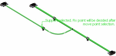
Selecting another object in the geometry tags it as Move.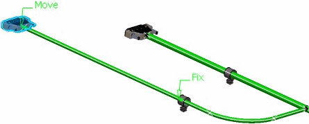
The Length Tolerance dialog box is also displayed.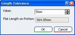
Notes:
- Devices are always tagged as Move.
- You can double-click any of the tags to swap their positions.
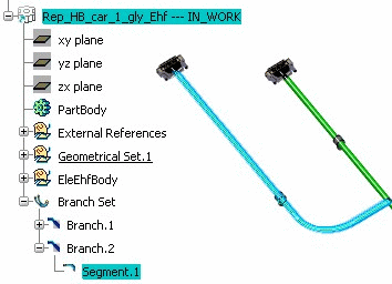
- The Segment's icon in the specification tree appears like this:
Enter a positive value or a negative value in the Value field to specify a positive or negative tolerance value.
Note: You can also enter a equation directly into the Value field. For example, 80mm - 77.158mm and click anywhere outside dialog box to see result 02.842mm before clicking OK.
Click OK. The segment length is increased or decreased by the value specified. The specification tree shows the applied length tolerance to Segment.1.
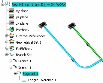
Right-click the segment and select Properties. The Properties dialog box shows that the LengthTolerance parameter is set to true.

Notes:
- You can apply more than one length tolerance value to the same segment. However, it must be applied over different portions of the same segment (not overlapping).
- You can apply length tolerance to a flattened geometry that has been extracted from 3D harness.
- If a segment, support, and/or protective covering are removed during the synchronization, and if a length tolerance was linked to any of these removed elements, the effect of the tolerance will be removed.
- You cannot scale a segment to which length tolerance has been applied.
- If both Design Length and Flat Length have been increased, this Length Tolerance value is maintained on the Segment portion even after the 3D flattened geometry Synchronizing Your 3D Flattened Geometry.
Important: - If length tolerance is used on a flattened geometry that has not been flattened in coarse mode, the result may not be what you expect.
- Length tolerance cannot be applied on a Roll section & vice-versa.