More About Analyzing Sketched Geometry | |||||
|
| ||||
Sketch Analysis Dialog Box
There are a few things that you need to know about Sketch Analysis dialog box.
This section describes the options available in the Geometry and Diagnostic tabs. For reference information about the Projections/Intersections tab, see Analyzing Projections and Intersections.
Geometry Tab
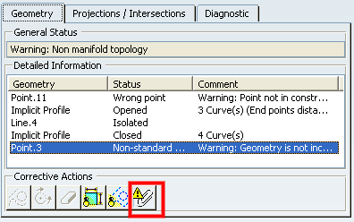
The Geometry tab displays information helping you know whether the sketch geometry is valid.
- General Status: analyzes several elements globally.
Note that "Implicit Profile" refers to all profiles except for profiles
created via Output Feature
 and Profile Feature
 .
For more information, see
Creating Output Features and
Creating Profile Features.
 - Detailed Information: provides a detailed status/comment on each geometrical element of the sketch.
- Corrective Actions
 :
according to the analyzed element you select and which is not correct,
you will be able to:
- turn this element into a construction element,
- close a profile that is not,
- erase a disturbing element,
- hide all constraints on the sketch,
- hide all construction geometries on the sketch and in the detailed information area of the Geometry tab.
Diagnostic Tab
The information on this tab displays a full diagnosis of a sketch geometry. It provides a global analysis of the sketch as a whole, and specifies whether individual geometrical elements in the sketch are under-constrained (under-defined), over-constrained (over-defined) or iso-constrained (well defined):
- Solving Status: provides a quick overall analysis of the sketch geometry.
- Detailed Information: provides a detailed status on each constraint and geometrical element of the sketch, and lets you know what type of element it is (geometry, constraint).
- Action
 : according
to the analyzed element you select, you will be able to:
: according
to the analyzed element you select, you will be able to:- hide all constraints on the sketch and in the detailed information area,
- hide all construction geometries on the sketch and in the detailed information area of the Diagnostic tab.
- erase geometry
![]()
More about the Reset Dependencies Option
If you created a complex fix together scenario in prior versions (from R14 to R17) by deselecting Add/Remove Dependencies in the Fix Together Definition dialog box, you can reset the dependencies removed using the Reset Fix Together Dependencies option of the Sketch Analysis dialog box.
When an inconsistency is detected in a fix together operation, a warning is displayed in the Detailed Information box and a new Reset Fix Together Dependencies command is available:

You are free to either reset the dependencies or leave it as it is. To reset the dependencies, select all the items with a Non-standard fix together definition status and click Reset Fix Together Dependencies.
Note the Reset Fix Together Dependencies command only appears when at least one geometry is missing from the fix together.
![]()
About Coincidence Constraints Automatically Added to Profiles
Whenever you create a sketch-based feature from a profile, the system automatically creates coincidence constraints on the overlapping points of the profile to interpret it as closed.
This
is the reason why once the sketch-based feature is created, coincidence
constraints are visible in the detailed information list of the Sketch
Analysis
![]() results.
results.