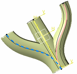
Double-click Sketch.1 to edit it:
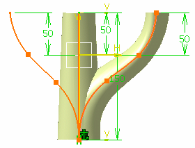
Click Output Feature
 in the Tools toolbar.
Select Spline.1.
An output feature is created as a standard element, but it is
viewed
with a thicker graphic property in the Sketcher. In order to keep the
properties defined by the user, the thickness is modified only if the
geometry has the same thickness as when the geometry was created.
It is made available in the 3D area and you can update it independently
from the sketch, once in the 3D area. It is independent from the sketch
3D geometry.
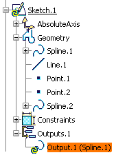
It is integrated as such both into the Parent/Children view and the
specification tree:
Right-click Spline.1 and select Properties.
Click the Graphic tab in the Propertiesdialog box that appears.
Change the color and the line type to distinguish
Spline.1
even more from other elements.
Exit the Sketcher
workbench.
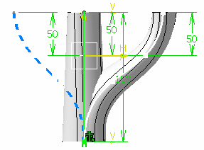
The output feature can now be visualized with the
spline properties it has been applied to.
Go to the Generative Shape Design workbench.
Click Multisections Surface
 .
.
Select Sketch.4 and Sketch.5 in the Multi-sections Surface Definition dialog box that appears.
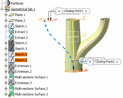
Select the Spine tab.
Select Output.1 (Spline.1) from the specification tree.
Click OK.
The surface is created.
